
User's Manual

C
A
B
D
www.art-tech.com
8
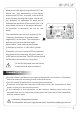
Working modes' option
MIX: delta-wing or V type tail-wing mode
NOR: normal mode
Operating direction display
REV.: Reverse setting
NOR.: Normal setting
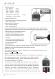
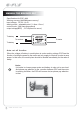
Stick lever spring tension adjustmentThe stick spring tension can be adjusted. The
operating feel of the aileron, elevator, and rudder sticks can be individually adjusted.
Remove the four transmitter rear case
screws and remove the rea case.
Adjust the spring strength by turning
the screw of the channel you want
to adjust.
Close the rear case and tighten The
four screws.Stick length adjustment.
Turn the head of stick.
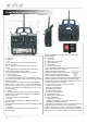
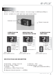
TRAINER JACK
Connects the trainer cord when using the trainer function (The trainer cord is sold
separately), see part 8 for the details of the trainer function.
BATTERY COVER
Use when replacing the battery. Slide the cover downward while pressing the
part marked PUSH
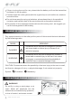
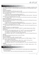
MODE I AND MODE II SETTING
Before setting mode I and mode II ,please turn off the power of the plane.
Press the sub button, enter into the Mode I and Mode II setting
menu.Before Mode Setting, please unplug the power supply of
the plane.Adjustment of joysticks
The screws for mode setting are in the rear cover. as
shown in
the figure:
and the screws C
Therefore, for mode I, loosen
screws B and D. For mode II, loosen thescrews B and D, tighten
And then set the second switch of the switch set U to set the right mode.
The screws A and B play the role of suppressing springs;
and D play the role of adjusting resist force.
the screws A and C, tighten the
1.
2.
Channel display
AIL.: Aileron (CH1)
ELE.: Elevator (CH2)
THR.: Throttle (CH3)
RUD.: Rudder (CH4)
Aeroplanes
: flap control
Helicopters: pitch control
(CH6)