
User's Manual
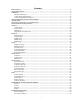
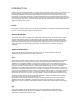
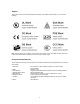
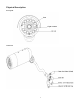
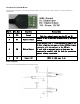
Table Of Contents
- Main Features
- Physical Description
- Installation
- Network Camera Screen and Setup Window
- Operating Bar
- Viewing the camera from your mobile phone
- Network Camera Setting Interface
- Camera
- Alarm
- SD Functions
- Tools
- SPEEDREAD YOUR NETWORK CAMERA
- ADVANCED SETTINGS
- DEFAULT SETTINGS
- SPECIFICATIONS
- TROUBLESHOOTING
- GLOSSARY OF TERMS

Genneral I/O Terminal Block
This Network Camera provides a general I/O terminal block which is used to connect external input / output devices. The pin definitions are
described below.
Pin No. Pin Name Function Description
4 GND Ground
This is a signal ground use for DI and DO
3 DI Digital Iutput
Connect to GND to activate or deactivate by software
setting
2 DO Digital Output
With a maximum load of 1A and maximum voltage of 60V
DV,this output has an open-collector NPN Darlington
transistor with the emitter to the GND pin.
If used with an external relay,a diode must be
connected in parallel with the load,for protection
against voltage transients.
1 12V Power +12V 12VDC ± 10%, max. 0.4A
DI/DO Diagram
Please refer to the following illustration for the connection method.
10