
User's Manual


aee.com
10
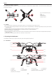
Figure 11
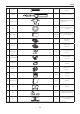
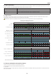
Indicators on the remote control
Power indicator Status indicator(tri-color light)
Photo shooting & video
recording indicator
Red light ●
Red light ● /green light ● /blue
light ●
Green light ● Function status
Remaining ON N/A N/A Power on
Remaining ON Red light remains ON N/A Abnormal condition, as signal loss etc.
Remaining ON Blue light remains ON N/A
Indicates that signal connection is normal and the quadcopter is in the GPS
signal searching status�
Remaining ON Green light remains ON N/A Indicates that signal connection is normal and GPS signal is good
Remaining ON Blue light blinks N/A
Indicates that the quadcopter is in the GPS signal searching status and in the
auto ight mode (low-battery auto landing); now the remote control can regain
control of the quadcopter via the S4 switch�
Remaining ON Green light blinks N/A
The rst situation indicates that the GPS signal is good and the quadcopter is in
the auto y mode (1. auto landing, or 2. low-battery auto landing); now the remote
control can regain control of the quadcopter via the S4 switch�
The second situation indicates the joystick calibration status. During calibrating,
the indicator blinks. When the green light will go out, the calibration completes
successfully. If the calibration does not complete, the green indicator will continue
blinking�
Remaining ON N/A Blinks once
Blinking once during Capture: once photo is taken (only to the AEE S61 camera
mounted on the quadcopter)�
Remaining ON N/A Blinking Slowly The camera is recording
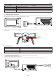
1) When Remote control battery power is low, a warning alert sounds (di didi di didi…).
2 ) When the remote control or the APP sends a command for video recording, the video recording indicator on the remote control will blink.
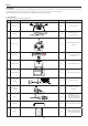
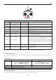
3 Preparing Propellers
uadcopter adopts 10-inch propellers, with black and gray color propeller nuts. Propellers are consumable items. Please purchase these accessories separately, if
necessary�
3.1 Introduction
Propellers Gray (1045) Black (1045 P)
Diagram
Assembly Location Attach to the motor shaft without "P" mark Attach to the motor shaft with "P" mark
Installation Location
Lockup: Tighten propeller in this direction
Symbol Description Unlock: Loosen propeller in this direction
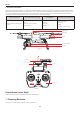
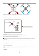
3.2 Assembling Propellers
(As shown below) Prepare two propellers with gray nuts and two with black nuts. Attach propellers with gray nuts to motor shafts without "P" marks, and attach
propellers with black nuts to motor shafts with "P" marks� Tighten propellers as per the appropriate locking direction�