
Installation Instructions

ns for appearance
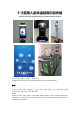
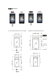
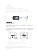
闸机头示意图如下图所示。
The schematic diagram of the gate is shown in the figure below.
注意:若线缆接口与图示不同,参见下一页线缆补充(以实物和接线图为准)
Note: If the cable interface is different from the illustration, see the cable supplement on the next
page (subject to the actual product and wiring diagram)
B
外观部分指示说明
B Instructions for appearance
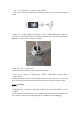
①根据安装现场的需求,在闸机上的空间位置,一般中间或前侧,开一个直径 35mm
的孔,
如图所示,⊕为建议开孔位置。
①
According to the requirements of the installation site, a space of 35mm in diameter is generally
opened in the middle or front of the gate, as shown in the figure, ⊕ is the recommended
opening position.
单通道闸机 Single channel gate 双通道闸机 Double channel gate
注意:开孔位置应根据实际应用场景和闸机类型,35mm 仅为参考值。
Note: The position of the opening should be based on the actual application and the type of
gate, 35mm is only a reference .
②拧下闸机头立柱最下方的螺母,将线缆从螺母穿出,取下螺母,如图所示。
Unscrew the nut at the bottom of the gate, pass the cable through the nut, and remove the nut,
as shown in the figure.