REV A Contents 1. Application........................................................................................................................................................................1 2. Declarations ......................................................................................................................................................................2 Safety precautions .............................................................................................................
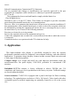
REV A Federal Communications Commission(FCC) Statement You are cautioned that changes or modifications not expressly approved by the part responsible for compliance could void the use’s authority to operate the equipment FCC-Class B This equipment has been tested and found to comply with the limits for a Class B digital device, Pursuant to part 15 of the FCC Rules. These limits are designed to provide reasonable protection against harmful interference in a communications.
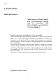
REV A 2. Declarations Safety precautions With respect to electric shock, Fire and mechanical hazards only in accordance with IEC、UL60950-1 and CAN/CSA C22.2 No. 609501-1 Regular maintenance and calibration are recommended Please note that liquid crystal displays such as the C14S\G11S do not have a failure rate of zero and image parameters may change over time (e.g. luminance or discoloration). Please ensure that all measures are taken to prevent injuries or incorrect diagnoses.
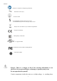
REV A Attention: Consult the accompanying documents Alternation current (AC) Protective earth CAUTION:Risk of electric shock. Do not open. ATTENTION:Risque de choc electrique, Ne pas ouvrir Dispose of in accordance to your countries requirements European comformity China Quality Certification UL approval mark Conformance with FCC Rules and Regulations China Rohs symbol Danger: There is a danger to life if the warning information is not observed.
REV A components presents a danger to life! Only use a perfect power supply cable A damaged power supply cable may result in a fire or electric shock. When disconnecting the power supply cable, always do so by holding the plug. Only use the same type of fuse 2A/250V Do not insert any objects into the housing Objects inserted into the housing may result in damage to the unit or personal injury. Do not place any objects on top of the units Penetrating liquids may result in a fire or electric shock.
REV A Mounting information: The stability of the display must be guaranteed following mounting of the foot/holder. The immersion depth of the mounting screws has to be 10 to 12 mm including a 3 mm VESA mounting plate. (See also table "Mounting screws" on the following). All these requirements are satisfied when using the original foot. All requirements must be observed when using customer-specific mounting solutions.
REV A Care of unit / cleaning agents − The front panel is extremely sensitive to mechanical damage. Avoid all scratches, knocks etc.! − Remove water drops immediately; extended contact with water dismonochromes the surface. Clean the front panel when dirty using a micro fiber cloth and, if necessary, a glass cleaning agent*. Only clean housing parts using a cleaning agent for plastics*. z Note: Do not use cleaning agents containing solvent, e.g.
REV A 3. Installation Provide adequate ventilation Ventilation slots are located on the rear of the housing. Ambient temperature The permissible ambient temperature range must not be violated. Minimize reflections The display should be positioned so that reflections of lights, windows, furniture with shiny surfaces or light-monochrome walls do not appear on the screen. Minimize mirroring In order to reduce mirroring on the unit, ceiling lighting or reflected light (no dazzling) should be used.
REV A 4. Start-up Caution In order to ensure safe operation of the equipment, close attention must be paid to the information contained in this Instruction Manual as well as the warnings in Section 2 "Safety precautions". Caution Information for end customer None of the settings must be changed on site by the user, otherwise the guarantee is canceled. This also applies to settings made using the HL1916 keys. These are therefore locked for certain applications.
REV A 4.1.2 Cable (attaching) Connect the cables to the display. Connect the power cable 15-pin Sub-D connector: the flat panel display can be connected to the computer system using the Sub-D connector.
REV A OSD menu. DVI connection: The connection to the computer can also be made via the digital single link or via the analog channel of the DVI connection. The picture quality, noise immunity and radiated interference of the complete system depend on the cable quality and length. Serial connection: you can connect the display via the 9pin D-SUB connector to the computer for firmware updating. 4.1.3 Little cover (attaching) Lead the monitor end of the cables through the little cover’s cable duct.
REV A − Adjust the brightness so that image sections with 5% and 0% blackness still visibly contrast from one another. − Adjust the contrast so that image sections with 95% and 100% whiteness still visibly contrast from one another. To adapt the luminosity to the ambient lighting, adjust the backlight brightness (note: 300 cd/m² factory setting is then modified). 4.5 Screen saver A screen saver function should be used in order to reduce "image sticking" which can occur in TFT displays.
REV A 5. Connections 5.1 Connecting the flat panel display Note All screening precautions contained in the corresponding EMC guidelines must be observed. If these guidelines are not observed, interference signals could penetrate the monitor. Information on cable installation Only screened cables are permitted for the signal connections. All connectors should be of screw or locking types (as far as possible). Signal and power cables must not be routed in the same duct.
REV A to the 15-pin Sub-D connector (female). DVI socket With DVI digital signal. 5.5 Power supply connection Note Device fuses can not be exchanged outside of the repair centers. The display power supply is connected using an appliance plug. Only use the power cable supplied in the delivery, or a cable with PE conductor and appliance socket to DIN 49 547, IEC 320. Caution A power cable with PE conductor must be used which corresponds to the safety requirements of the respective country of use. 5.
REV A 6. Adjustments 6.1 Picture adjustment This section describes the settings for operation of the flat panel display with a video source. The most important settings are: Adjusting the graphics memory of the video source As with all monitors, the flat panel display also has certain limits, e.g. maximum resolution and vertical frequency. The graphics adapter must be set when using the flat panel display such that the limits are observed.
REV A • Control again the black value did not change. In case it did you need to duplicate the two previous steps until it does not change anymore (cause: pedestal). Increase the contrast level until the measurement device no longer detects an increase in luminance. Once this is achieved, decrease the contrast level slightly (1 or 2 steps is generally sufficient). At this point, the display is configured for optimal performance with the installed graphic board.
REV A 6.3 OSD menu 6.3.1 Keys assignment and operation LED A “dynamic help for keypad function” is available for each menu: it explains the role of each key depending on the OSD menu window, which is currently active. 6.3.2 Key functions without active OSD menu Key Action Menu Activate OSD Up Adjust Backlight Down Analog Input auto balance * Scenario in case all signal sources is available. If not, the signal from the next available source will be displayed. 6.3.
REV A Exit Except "Exit OSD" menu In "Exit OSD" menu One menu level upwards (settings are retained) Return to main menu (settings are retained) 6.3.4 Submenu calls Press the “Menu” key while the OSD is active, the function icon will jump to next line. Pressing the “Up” key, the coordinate submenu will be selected. 6.3.5 Locking of OSD menu Key(s) Action In a sequence Set, Lock or unlock OSD If the OSD is locked, it is only possible to Up, Up ,Up switch over the source (see Section 6.3.2). 6.3.
REV A 6.4 Description of the menus Main Menu Function Adjustment range Description 0…255 Adjustment of contrast This allows the brighter area to be seen more distinctly. The center point is in 128 position. Note: for DVI-D signals the Contrast setting is optimized. Manual changes are not recommended. Brightness 0…255 It is used to adjust the Brightness of the monitor. The center point is in 255 position. This allows the darker area to be seen more distinctly.
REV A The auto functions are used to assist the automatic setting of parameters. The quality of settings depends on the picture contents and the type of synchronization. Corresponding items in the OSD can adjust all settings finely. Auto function (Analog input only) Execute AutoBalance Auto -Config Auto adjust on mode change Language On/Off The selected auto functions are executed. Note: The quality of the function depends on the applied picture contents.
REV A Quit OSD menu Accept changes Reject changes Quick OSD menu and either save or reject the changes. If you have reached this menu unintentionally, you can return to the main menu using the EXIT key. If this message is displayed, you do not have the authority to carry out the changes in the OSD menu. Please contact your servicing partner in this case.
REV A 7.
REV A 8. Technical data All technical data are valid after a warming-up period of 2 hours. 8.1 Display Type Display area Picture diagonal Native resolution Pixel organization Pixel pitch Contrast ratio Horizontal viewing angle Vertical viewing angle Backlight Brightness Lifetime backlight TFT,color active matrix 376.32 mm x 301.056 mm 19" or 48 cm 1280 x 1024 (full-screen format) 3 vertical sub pixels 0.294 mm x 0.
REV A multi-sync CRTs). In the same way, resolutions higher than 1280 x 1024 can be reduced and then displayed. (Caution: depending if the timing is frame buffered or frame sync, image information might get lost; the gray levels - the color depth for color images - will also be reduced and might be visible) H frequency, V frequency Timing recognition 8.4 Inputs/outputs 8.4.
REV A Vertical frequency 50.0Hz - 85.0 Hz (Non-Interlaced) 50.0Hz - 85.0 Hz (Non-Interlaced) Video Signal Analog RGB Digital RGB Sync. Signal Separate Sync. (TTL) Composite Sync. Sync on green TMDS Pixel Clock 25.0MHz -140.0MHz 25.0MHz -140.0MHz Input connector Mini D-sub 15Pin DVI-D 8.5 Controls and connection elements Left Side Rear Four keys for OSD menu, operation-LED • Power switch •Power supply connection • DVI socket • 15-contact 3-row Sub-D socket • RS 232 sockets Sub-D 9 pin 8.
REV A 8.7 Climatic conditions Operation Ambient temperature range Temperature gradient Relative Humidity Atmospheric pressure +10.. +40 °C Max. 5 °C/h 10-80%, no condensation 700hPa to 1060hP a Transport and storage (packed) Ambient temperature - 20 ... + 60°C range Temperature gradient Max.
REV A 8.8 Mechanical requirements Operation Vibration Shock According to EN 60068-2-6 10 ... 58 Hz with ± 0.075 mm deflection 58 ... 500 Hz at 10 m/s² According to EN 60068-2-27 (single shock) 150 m/s², 6 ms No permanent shock allowed in operating conditions Packed unit Vibration According to EN 60068-2-6 5 ... 9 Hz with ± 3.5 mm deflection 9 ... 500 Hz at 10 m/s² Shock According to EN 60068-2-27 (single shock) 250 m/s², 6 ms (in storage packaging) According to EN 60068-2-29 (permanent shock) 8.
REV A 8.
REV A 9. Dimensional drawings All dimensions in mm. 9.
REV A 10 Remarks and contact address Invalidity of guarantee All unauthorized electrical or mechanical alterations on or in the unit result in loss of the guarantee. Information on the Instruction Manual For clarity reasons, this Instruction Manual does not contain all detailed information on this product. Your attention is additionally drawn to the fact that the contents of this Instruction Manual are not part of a previous or existing agreement, commitment or statutory right and do not change the latter.