User Manual 19 inch Color LCD Display Model: HL1916LA, HL1916LB, HL1916LBT, HL1916 VA, HL1916 VB(C15S) Rev.
Contents 1. Application........................................................................................................................................................................1 2. Declarations ......................................................................................................................................................................2 3. Installation........................................................................................................................
1. Application This high-resolution color display is specifically designed to meet the rigorous performance standards needed for diagnostic, interventional radiology, and other medical applications. To guarantee image integrity, features include accurate signal conversion and a wide range of interfacing options. Compact design -Low weight and small size with improved performance make the color flat panel display HL1916 SERIALS preferable to conventional CRT monitors.
2. Declarations Safety precautions Medical Equipment With respect to electric shock, Fire and mechanical hazards only in accordance with ANSI/AAMI ES60601-1:2005&CSA C22.2 No.60601-1:2008 WARNING: To avoid risk of electric shock, this equipment must only be connected to a supply mains with protective earth. APPLIANCE COUPLER or separable plug of is used as isolation means to isolate the equipment from mains supply.
components presents a danger to life! Only use a perfect power supply cable A damaged power supply cable may result in a fire or electric shock. When disconnecting the power supply cable, always do so by holding the plug. Only use the same type of fuse T2A/250V Do not insert any objects into the housing Objects inserted into the housing may result in damage to the unit or personal injury. Do not place any objects on top of the units Penetrating liquids may result in a fire or electric shock.
For certain applications, the video earth can be separately connected to the PE via the additional PE connection in the plug panel (observe IEC 60601-1). Close the plug panel using the provided cover , and secure using the screws. Turn switch off and then remove power cord. Mounting information: The stability of the display must be guaranteed following mounting of the foot/holder. The immersion depth of the mounting screws has to be 10 to 12 mm including a 3 mm VESA mounting plate.
Please see 4.1.4 for details. The permissible ambient temperature range (5 °C ... 35 °C) must not be violated. Do not subject device to unnecessary shocks. Take care when transporting! Use the original packaging! The panel in particular should be protected against shocks. When touching the panel surface, the mechanical contact or an electrical discharge may cause a brief disturbance in the picture quality. Care of unit / cleaning agents − The front panel is extremely sensitive to mechanical damage.
European comformity China Compulsory Certification TUV approval mark 3. Installation Provide adequate ventilation Ventilation slots are located on the rear of the housing. Ambient temperature The permissible ambient temperature range must not be violated. Minimize reflections The display should be positioned so that reflections of lights, windows, furniture with shiny surfaces or light-colored walls do not appear on the screen.
4. Start-up Caution In order to ensure safe operation of the equipment, close attention must be paid to the information contained in this Instruction Manual as well as the warnings in Section 2 "Safety precautions". Caution Information for end customer None of the settings must be changed on site by the user, otherwise the guarantee is canceled. This also applies to settings made using the HL1916 SERIALS keys. These are therefore locked for certain applications.
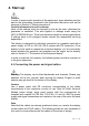
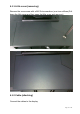
4.1.1 Little cover (removing) Remove the one screws with a M4 Slot screwdriver (one turn suffices).Pull down the little cover and then open the little cover and remove it 4.1.2 Cable (attaching) Connect the cables to the display.
VGA connector: the flat panel display can be connected to the computer system using a VGA Cable on D-sub connection for analog signal. The display is adapted using an OSD menu. BNC connector: the flat panel display can be connected to the video camera using a special BNC-VAG Cable for analog signal. The display is adapted using an OSD menu. DVI-D connection: The connection to the computer can also be made via the digital single link.
with four M4x12 screws. Move the button of stand base towards the right, and lift the monitor, and then turn the monitor by 90 degrees. Button of stand base 4.1.4 Mounting Use Remove the stand base according to the contrary way in 4.1.3. Fix the mount by mounting screws (see page 6 table Mounting Screws for details).
4.2 Switching on the display Switch on the flat panel display using the power switch. The operation LED lights up (color: green, provided the timing has been recognized – please refer to section 7 "Fault diagnostics"). 4.3 Adjusting the image geometry The display automatically recognizes the used standard, and set-up values for each standard are preprogrammed. However, depending on the graphics card used, it may still be necessary to align and size the picture for the selected standard (see Section 6.
4.5 Screen saver A screen saver function should be used in order to reduce "image sticking" which can occur in TFT displays. It is high risk to display a static graphic over half an hour. Image sticking is the effect where a faint image of the previous screen contents can still be seen after the display contents have changed. By using a screen saver with permanently changing screen contents, unnecessary effects of the same image are avoided.
5. Connections 5.1 Connecting the flat panel display Note All screening precautions contained in the corresponding EMC guidelines must be observed. If these guidelines are not observed, interference signals could penetrate the monitor. Information on cable installation Only screened cables are permitted for the signal connections. All connectors should be of screw or locking types (as far as possible). Signal and power cables must not be routed in the same duct.
5.4 Analog and digital inputs (DVI,VGA,DP, BNC) DVI socket With DVI digital signal through DVI cable. VGA socket With VGA cable for VGA input. DP socket With DP digital signal through DP cable. BNC connector Use BNC-VGA cable (optional) for BNC input. 5.5 Power supply connection Note Device fuses can not be exchanged outside of the repair centers. The display power supply is connected using an appliance plug.
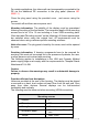
2 D- 3 D+ 4 GND 6. Adjustments 6.1 Picture adjustment This section describes the settings for operation of the flat panel display with a video source. The most important settings are: Adjusting the graphics memory of the video source As with all monitors, the flat panel display also has certain limits, e.g. maximum resolution and vertical frequency. The graphics adapter must be set when using the flat panel display such that the limits are observed.
measured value no longer changes). Once this is achieved, increase the brightness level slightly until the display is just above the absolute lowest black level (one step is generally sufficient). Similarly, set the white level using a 100%-white test pattern and the measurement device. Only the contrast level should be adjusted to ensure that the black level remains unchanged. • Control again the black value did not change.
6.3 OSD menu 6.3.1 Keys assignment and operation LED Menu Up Down Set LED A “dynamic help for keypad function” is available for each menu: it explains the role of each key depending on the OSD menu window, which is currently active. 6.3.2 Key functions without active OSD menu Key Action Menu Activate OSD Up Adjust the Backlight quickly at “key lock” mode. Down To set the picture more nature at VGA mode & “key lock” mode.
6.3.3Key functions in the OSD menu Key(s) Menu Up Down Set Situation Always Slide controller Command Slide controller Except "Exit OSD" menu In "Exit OSD" menu Action Jump to next line Increase value "Enter key" Decrease value One menu level upwards (settings are retained) Return to main menu (settings are retained) 6.3.4 Submenu calls Press the “Menu” key while the OSD is active, the function icon will jump to next line. Pressing the “Up” key, the coordinate submenu will be selected. 6.3.
Display Settings Contrast 0…100 Backlight 0…255 Color Color1 Color2 Color3 User R G B Gain R G B Bias 0…255 H Position (Analog only) V Position (Analog only) 0…255 already optimized for digital signals. Manual changes to these values are not recommended, as this can result in an impairment of picture quality (loss of grayscales). Adjustment of contrast. This allows the brighter area to be seen more distinctly. The center point is in 50 position.
Input Source Auto Adjust (Analog only) DVI-D DP VGA Auto-Color ON / OFF Automatically get input signal match with the monitor Auto-Configure ON / OFF Automatically adjust the image display settings. Execute OSD Settings own pulse. Other digital signals which is lower than 1280 x 1024 can be adjusted. Analog signals can be adjusted in all supported resolution. Negative figure is adjusted to get softer image and positive figure is adjusted to get sharper image.
中文 to select the language of the OSD menu. English is the default. While in the English menu state the ”中文” font means to select to Chinese menu. And while in Chinese menu state the “English” font means to select to English.
7.
8. Technical data All technical data are valid after a warming-up period of 2 hours. 8.1 Display Type Display area Picture diagonal Native resolution Pixel organization Pixel pitch Contrast ratio Horizontal viewing angle Vertical viewing angle Backlight Brightness 4 dual CCFT (cold cathode fluorescent tube) MIN 230 cd/m² Factory setting: 180 cd/m² Lifetime backlight 50,000 hours typically for CCFT (applies to an ambient temperature for the backlight of 25°C) of TFT, color active matrix 376.32m x 301.
8.4 Inputs/outputs 8.4.1 Analog signal input VGA input Via VGA socket, single link BNC Input Via special BNC-VGA cable to the VGA socket 8.4.2 Digital signal input DVI-D input DP input DDC Via DVI socket , single link Via DP socket Via DVI 8.4.3 Serial and USB interfaces RS232 USB Via PS2 connector B connector(HL1916LB, HL1916LBT) 8.4.
Display Port DVI EDID datum EDID via DVI I2C bus Display Port 1.1 Receiver 4 main Lanes Display Port: 600mV for each differential line Impedance: 100 ohm per differential pair DP EDID datum EDID via AUX channel 8.5 Controls and connection elements Front Side Rear Four keys for OSD menu, operation-LED • Power switch •Power supply connection • DVI socket • DP socket • VGA socket • RS 232 sockets 6 pins PS2 • USB B connector(HL1916LB, HL1916LBT) 8.6 Mechanical design Item Set Width 416.
Temperature gradient Relative Humidity Atmospheric pressure Max. 7℃/h , no condensation 15%-85% 70 – 106 kPa Transport and storage (packed) Ambient temperature range Temperature gradient Relative Humidity Atmospheric pressure -20 -- +60℃ Max. 10℃/h, no condensation 10%-90% 70 – 106 kPa 8.8 Mechanical requirements Operation Vibration Shock According to EN 60068-2-6 10 ... 58 Hz with ± 0.075 mm deflection 58 ...
8.11 Touch screen Performance Mechanical Specifications Input Method Finger, gloved hand, or any other opaque stylus Touch technology Infrared rays interception detection, no special surface coatings Available size 19” Glass 3.0mm Double-sided AR glass Frame Deformation/Flatness <1.
9.
10 Remarks and contact address Invalidity of guarantee All unauthorized electrical or mechanical alterations on or in the unit result in loss of the guarantee. Information on the Instruction Manual For clarity reasons, this Instruction Manual does not contain all detailed information on this product. Your attention is additionally drawn to the fact that the contents of this Instruction Manual are not part of a previous or existing agreement, commitment or statutory right and do not change the latter.
FCC Statement: This device complies with part 15 of the FCC Rules. Operation is subject to the following two conditions: (1) This device may not cause harmful interference, and (2) this device must accept any interference received, including interference that may cause undesired operation. This equipment has been tested and found to comply with the limits for a Class B digital device, pursuant to part 15 of the FCC Rules.