BIGTIDE Customer Specification 32 LCD Monitor HL3116ST Rev 0.0 Name Last change: Dec 23, 2016 Department/Title R&D Engineer Date Dec. 2016 Torch Bigtide Digital Technology Co., Ltd.
Revision History Version 0.0 Date Dec. 26th, 2016 Last change: Dec 23, 2016 Author Modification Draft Torch Bigtide Digital Technology Co., Ltd.
CONTENTS 1 SCOPE ........................................................................................................................................ 5 2.ELECTRICAL PERFORMANCE ........................................................................................................ 5 2.1 Power Supply .................................................................................................................... 5 2.1.1 Power connector model ............................................................
6. PANEL DEFECT INSPECTION CRITERIA ...................................................................................... 24 6.1 Display Inspection................................................................................................................... 24 7. IR Touch Panel & Protection Glass .............................................................................................. 27 7.1 Installation .............................................................................................
1 SCOPE This document defines the performance requirements of 32 inch TFT UHD LCD monitor for medical use. This high-resolution UHD LCD monitor is specifically designed to meet the rigorous performance standards needed for diagnostic applications in medical environment and modality use and can be used for X-ray, MRI, PACS and other medical systems requiring a very high level of image quality for examination and control purpose. The monitor is designed to meet all rigorous medical safety requirements.
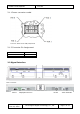
- Power Consumption : <130W 2.1.1 Power connector model Connector: Molex 39-30-1080,2*4P,4.2mm 2.1.2 Connector Pin Assignment Pin 1, 2, 5 3, 4, 6, 7, 8 Function +Vcc GND 2.2 Signal Interface Blue area details: DVI-D DisplayPort Service Last change: Dec 23, 2016 DC IN Torch Bigtide Digital Technology Co., Ltd.
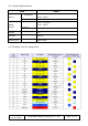
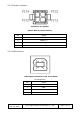
2.2.1 Signal Specifications Item Signal Input (DP1.2) SPEC Frequency Pixel clock Frequency VIDEO IN(DVI) H 31 ~ 160 kHz V 24~ 120Hz 25–550MHz H 31 ~ 100 kHz V 24~ 120Hz Pixel clock 25–350MHz DSub15 TTL USB port Type B Speaker port 5559-4 Molex 2.2.2 Display Port Pin Assignment Last change: Dec 23, 2016 Torch Bigtide Digital Technology Co., Ltd.
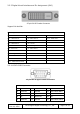
2.2.3 Digital Visual Interface and Pin Assignment (DVI) 25-pin DVI-D Female Connector Support DVI dual link.
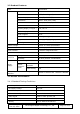
2.2.5 Speaker Interface Connector for speaker (Molex Mini-fit, Molex 5559-4) Pin Signal 1 SPKR1(-) 2 SPKR1(+) 3 SPKR2(-) 4 SPKR2(+) 2.2.6 USB Interface USB Type-B connector for IR Touch Panel Pin Assignment Last change: Dec 23, 2016 Pin Signal 1 VCC DC: +5V 2 Data- 3 Data+ 4 GND Torch Bigtide Digital Technology Co., Ltd.
2.3 Product Features Item LCD Specification Panel Module INNOLUX Size 31.5” (80 cm diagonal) Active Display Area 698.4 (H) x 392.85 (V) mm Resolution 3840 x 2160 pixel (UHD) Pixel Pitch 0.181(H) x 0.181(V) mm Luminance R315DJJ-K31 650cd/m2 (Panel min.) Viewing Angle (H VType.) 178°, CR>10 Color imaging Yes Color support 10 bit Contrast Ratio 1700:1 (panel typical) Response time 9.5ms(typical), gray to gray.
- Luminance meter Minolta CA-310 or equivalent - Graphics card Nvidia Quadro equivalent K4000, K4200 or 2.4.2 Brightness Factory Preset DICOM 575(Default): Lmin=0.7±0.2 cd/m² Lmax = 575±45 cd/m² DICOM 550: Lmin=0.7±0.2 cd/m² Lmax = 550±45 cd/m² DICOM 500: Lmin=0.7±0.2 cd/m² Lmax = 500±40 cd/m² DICOM 300: Lmin=0.7±0.2 cd/m² Lmax = 300±25 cd/m² Max.
2.4.6 White Balance x=0.313±0.03 y=0.329±0.03 at DLL255 (Note 7) 2.4.7 Gamma Curve Within ± 10% tolerance of calculated value 2.4.8 PIP Window Size: 1920x1920 pixel Location: see below blue PIP Image area. The button icon located in the lower right corner to indicate the touch point for closing the window. Note1: Test Equipment Setup The measurement should be executed in a stable, windless and dark room between 20 minutes after the backlight at the given temperature for stabilization of the backlight.
Note2: Viewing angle is measured as follow: Note 3: Definition of contrast Ratio (CR): The contrast ratio can be calculated by the following expression. Contrast Ratio (CR) = L255 / L0 L255: Luminance of gray level 255 L 0: Luminance of gray level 0 CR is corresponding to the Contrast Ratio of the center point at Figure in Note 5. Note 4: Definition of Luminance of White: Luminance of white at center point. Note 5: Definition of brightness uniformity,test separately half panel 5 points.
Note 6: Definition of response time is as follows: Sum of Ton, Toff When the display data is changed from white to black, response time is measured Note 7: Definition of Color Chromaticity (CIE 1931) Color coordinate of Red , Green, Blue & White at center point . Last change: Dec 23, 2016 Torch Bigtide Digital Technology Co., Ltd.
3.OPERATING GUIDE 3.1 Operation display methods The display no physical buttons. The host uses the DDC/CI command to set the display through the DP connector. 3.2 DDC/CI Communication Command Requests from host to display use the following message structure: Destination: 0x6E – standard display slave address for writing Source: 0x51 – standard host address Length: 0x80 + number of bytes following this byte, not including checksum.
b. 0xBB 0x44 – return active sources. 0x30=none, 0x31= DisplayPort only detected, 0x32=DVI (for PIP), 0x33=DVI + DP c. 0xBB 0x0D – return board temperature as an ASCII decimal integer number in degrees C d. 0xBB 0xED – return monitor runtime as an ASCII decimal integer number of hours monitor has been on since manufacture. Internal counter should be accurate to at least a minute. e. 0xBB 0xEE – return resolution of DVI input video as a pair of short unsigned binary values.
4. MECHANICAL SPECIFICATIONS 4.1 Installation Note: The top and bottom joints are fully same; we put one joint with crews and one monitor in a carton. (One carton only has one monitor and one joint ). 4.1.1 Monitor dimensions Unit:mm Last change: Dec 23, 2016 Torch Bigtide Digital Technology Co., Ltd.
Item Housing components Visible surface Set Plastic screen Approx. 698mm×393mm Ventilation slots In rear panel Degree of protection IP20 to DIN40050 Cable cover At rear 4.1.2 VESA Hole 100mmx100mm,100mmx200mm Attention: The maximum depth of VESA hole which can be inserted is 10mm. Last change: Dec 23, 2016 Torch Bigtide Digital Technology Co., Ltd.
4.2 Screen Quality 4.2.1 H/V outline position H: |L-R|≤1.5mm V: |U-D|≤1.5mm 4.2.2 Outline edge position ∣A-B∣≤1.0mm ∣E-F∣≤1.0mm Last change: Dec 23, 2016 ∣C-D∣≤1.0mm ∣G-H∣≤1.0mm Torch Bigtide Digital Technology Co., Ltd.
4.2.3 Structure width position ∣A-B∣≤2.0mm 4.3 Packaging Each monitor is packed in its individual carton. The carton uses below safety symbols. Please read them carefully. This end up. Keep dry. Fragile, handle with care Last change: Dec 23, 2016 Torch Bigtide Digital Technology Co., Ltd.
The Max. stack quantity is 3. Transport temperature: -20C to 60C Transport air pressure: 70 – 106 kPa Transport humidity: 5- 95% (non –condensing ) Recycle 4.3.1 LCD Package dimension and weight Box Outer box size of Width (mm) 955 Depth (mm) 235 Height (mm) 625 Weight without Package Gross Weight 14kg 25.5kg 5.ENVIRONMENT CONDITIONS 5.1 Operation Temperature Ambient temperature range +10 -+35℃ Ambient humidity 10%-80% Temperature gradient Max.
5.3 Mechanical requirements Operation Random vibration, 1 G rms 5-200Hz for 2 hours duration, in the vertical direction. Random vibration, 0.5 G rms 5-200Hz for 1hour duration, in the horizontal plane, in a direction perpendicular to the front face of monitor. Random vibration 0.5 G rms 5-200Hz for 1 hour duration, in a horizontal plane, in a direction parallel to the front face of the monitor.
5.5 Safety specifications IEC/EN/UL60601-1, ANSI/AAMI ES60601-1&CSA C22.2 No.601.1-M90 Safety standards Approvals c TUV us, FCC, CB Protection class Protection class III Conformity CE 5.6 Electromagnetic compatibility Comply with IEC/EN60601-1-2(Class B), FCC Part15, CISPR11(EN55011). 5.
Backlight is considered defective when the luminance is 50% of the specified initial maximum luminance. 6. PANEL DEFECT INSPECTION CRITERIA 6.1 Display Inspection Last change: Dec 23, 2016 Torch Bigtide Digital Technology Co., Ltd.
(2)Line Defect Line defect is defined as a horizontal or vertical line that differs from adjacent lines in brightness at any gray level. Line defects will not exist anywhere on the screen. (3)Mura Not visible through 3 % ND filter or judge by limit sample. 6.2 Appearance Inspection Last change: Dec 23, 2016 Torch Bigtide Digital Technology Co., Ltd.
6.3 The other items see “LCD Panel Inspection Specification—Model No.:R315DJJ-K31” Other Issues which are not defined in these criteria, shall be discussed with both parties, Customer and Supplier, for better solution. Circular(mm2) Last change: Dec 23, 2016 S≤0.05 0.05<S≤0.2 0.2<S≤0.3 S>0.3 Allowed N≤4 N≤2 Not Allowed Torch Bigtide Digital Technology Co., Ltd.
7. IR Touch Panel & Protection Glass 7.1 Installation The Touch Panel is an integral part of the display assembly. 7.2 IR Touch panel 7.2.1 IR Touch Specifications The monitor integrated IR touch. Item Active Area Response Time Frame Rate Touch Accuracy Input Method Output Form Touch Durability Minimum object sizes Single touch for touch Multi touch Multi touch Interface Transmission rate Working voltage Current No drift Specification 31.5 inch <15ms 125Hz ±2.
7.3 Protection Glass Specification 7.3.1 Outline Dimension 712.0±1.0(W)X409.0±1.0(H)X1.6±0.1(D),unit mm. 7.3.2 Construction HEA: High-Efficiency-Antireflection 7.3.3 Reflectance The brightness of the surface when measured at 10 degrees angle o incidence shall be no greater than 0.25% without bonding to panel. After bonding to panel, at an angle of incidence of between 8 and 15 degrees, the display screen reflectance shall be no greater than 1.0% with white light source 7.3.4 Surface Quality a.
0.040.1 ≤10 1025 ≤3 10 2 interval 0 ﹥=20mm 1 0 c. Stain The heavy or distinct stains visible under transmission inspection are not allowed. Light strains visible only under reflection inspection conditions are acceptable. Stains that do not exceed the circular or linear defect criteria are allowed. d. Fractures None allowed. 8. NOTICE FOR HANDING (1) When the module is assembled, it should be attached to the system firmly using all mounting holes.
(15) Pins of I/F connector should not be touched directly with bare hands. 9. VIDEO SPECIFICATION 9.1 VIDEO TIMING(Display Port) Display Mode VGA, 640 x 480 VESA, 800 x 600 VESA, 800 x 600 VESA, 1024 x 768 VESA, 1280 x 800 CVT VESA, 1280 x 800 VESA, 1280 x 960 VESA, 1280 x 1024 VESA, 1600 x 1200 VESA, 1680 x 1050 CVT VESA, 1680 x 1050 VESA, 1920 x 1080 VESA, 1920 x 1200 VESA, 2048 x 1536 VESA, 2560 x 1600 CVT VESA, 2560 x 1600 3840 x 2160 3840x2160 Horizontal Frequency (kHz) 31.5 37.9 46.9 48.4 49.3 49.
VESA, 2560 x 1440 VESA, 2560 x 1600 CVT 89.4 89.7 60.0 60.0 311.75 268.5 Note:① Last change: Dec 23, 2016 Torch Bigtide Digital Technology Co., Ltd.
Note ② FCC Statement: This device complies with Part 15 of the FCC Rules. Operation is subject to the following two conditions: (1) This device may not cause harmful interference, and (2) this device must accept any interference received, including interference that may cause undesired operation. Caution: Changes or modifications not expressly approved by the party responsible for compliance could void the user's authority to operate the equipment.