User Manual 19 inch Color LCD Display Model: HL1916SH Rev.
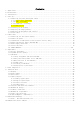
Contents 1. 2. 3. 4. 5. 6. 7. 8. 9. 10 Application................................................................................. 1 Declarations................................................................................ 1 Installation................................................................................ 6 Start-up.................................................................................... 6 4.1 Connecting the power and signal cables .............................................
1. Application This high-resolution color display with touch screen use is specifically designed to meet the rigorous performance standards needed for diagnostic, interventional radiology, and other medical applications. To guarantee image integrity, features include accurate signal conversion and a wide range of interfacing options. Compact design -Low weight and small size with improved performance make the color flat panel display HL1916S SERIAL preferable to conventional CRT monitors.
Appliance coupler or separable plug of is used as isolation means to isolate the equipment from mains supply. Accessory equipment connected to the analog and digital interfaces must be certified according to the respective IEC/EN standards (e.g.IEC/EN950 for data processing equipment and IEC/EN 60601-1 for medical equipment). Furthermore all configurations shall comply with the valid version of the System standard IEC/EN 60601-1-1.
Do not place any objects on top of the units Penetrating liquids may result in a fire or electric shock. Connection No contact to a patient must occur when handling the cables. Do not hurt yourself, when moving the display The display can be tilted backwards and forwards. Please, pay attention not to hurt yourself, when moving the display. Fingers or small objects may get stuck at the bottom of the display.
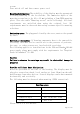
screws. Turn switch off and then remove power cord. Mounting information: The stability of the display must be guaranteed following mounting of the foot/holder. The immersion depth of the mounting screws has to be 10 to 12 mm including a 3 mm VESA mounting plate. (See also table "Mounting screws" on the following). All these requirements are satisfied when using the original foot. All requirements must be observed when using customer-specific mounting solutions.
The permissible ambient temperature range (5 °C ... 35 °C) must not be violated. Do not subject device to unnecessary shocks. Take care when transporting! Use the original packaging! The panel in particular should be protected against shocks. When touching the panel surface, the mechanical contact or an electrical discharge may cause a brief disturbance in the picture quality. Care of unit / cleaning agents − The front panel is extremely sensitive to mechanical damage. Avoid all scratches, knocks etc.
3. Installation Provide adequate ventilation Ventilation slots are located on the rear of the housing. Ambient temperature The permissible ambient temperature range must not be violated. Minimize reflections The display should be positioned so that reflections of lights, windows, furniture with shiny surfaces or light-colored walls do not appear on the screen. Minimize mirroring In order to reduce mirroring on the unit, ceiling lighting or reflected light (no dazzling) should be used.
If the display is to be used in a sequence of several displays, or if it is not exactly known whether the graphics card standard can be output by the display, refer to Section 5.1 "Connection of the flat panel display". In order to start the unit properly, the following steps should be carried out in the given sequence. 4.1 Connecting the power and signal cables Warning The display can be tilted backwards and forwards. Please, pay attention not to hurt yourself, when moving the display.
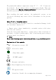
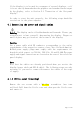
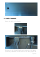
4.1.2 Cable (attaching) Connect the cables to the display. VGA connector: the flat panel display can be connected to the computer system using a VGA Cable on D-sub connection for analog signal.
display is adapted using an OSD menu. DVI-D connection: The connection to the computer can also be made via the digital single link. The picture quality, noise immunity and radiated interference of the complete system depend on the cable quality and length. DP connection: The connection to the computer can also be made via the DisplayPort connection. The picture quality, noise immunity and radiated interference of the complete system depend on the cable quality and length.
Button of stand base Note: the stand base is optional. 4.1.4 Mounting Use Remove the stand base according to the contrary way in 4.1.3. Fix the mount by mounting screws (see page 6 table Mounting Screws for details).
4.2 Switching on the display Switch on the flat panel display using the power switch. The operation LED lights up (color: green, provided the timing has been recognized – please refer to section 7 "Fault diagnostics"). 4.3 Adjusting the image geometry The display automatically recognizes the used standard, and set-up values for each standard are preprogrammed. However, depending on the graphics card used, it may still be necessary to align and size the picture for the selected standard (see Section 6.
5. Connections 5.1 Connecting the flat panel display Note All screening precautions contained in the corresponding EMC guidelines must be observed. If these guidelines are not observed, interference signals could penetrate the monitor. Information on cable installation Only screened cables are permitted for the signal connections. All connectors should be of screw or locking types (as far as possible). Signal and power cables must not be routed in the same duct.
5.4 Analog and digital inputs (DVI,VGA,DP) DVI socket With DVI digital signal through DVI cable. VGA socket Use VGA cable for VGA input. DP socket With DP digital signal through DP cable. 5.5 Power supply connection Note Device fuses can not be exchanged outside of the repair centers. The display power supply is connected using an appliance plug. Only use the power cable supplied in the delivery, or a cable with PE conductor and appliance socket to DIN 49 547, IEC 320.
Figure 4 Pin USB-B connector Signal 1 VBUS 2 D- 3 D+ 4 GND 6. Adjustments 6.1 Picture adjustment This section describes the settings for operation of the flat panel display with a video source. The most important settings are: Adjusting the graphics memory of the video source As with all monitors, the flat panel display also has certain limits, e.g. maximum resolution and vertical frequency. The graphics adapter must be set when using the flat panel display such that the limits are observed.
horizontal/vertical picture position and the picture sharpness. This can be carried out for the color flat panel display HL1916S SERIAL using an OSD menu. To optimize the display settings for the installed graphic board, and to ensure all gray levels are distinguishable, we recommend to adjust the brightness and contrast levels for and only for analog inputs.
edge. And similarly for an offset to the left, top or bottom. If the vertical lines are still slightly fuzzy, adjust the setting "Frequency/phase" (see Section 6.4 "Description of the menus"). 6.3 OSD menu 6.3.1 Keys assignment and operation LED Menu Up Down Set A “dynamic help for keypad function” is available for each menu: it explains the role of each key depending on the OSD menu window, which is currently active. 6.3.
While there is no sync in VGA input, there is instruction on the OSD to indicate that how to define the analog input as VGA input. Press and hold the ‘UP’ key for about 2 seconds, the monitor will change the analog input between VGA. The ‘Down’ key function is used to select input source and is enabled only when OSD menu is locked. This function can be enabled or disabled through OSD selection. This choice is in case all the signal sources are available.
Display Settings already optimized for digital signals. Manual changes to these values are not recommended, as this can result in an impairment of picture quality (loss of grayscales). Adjustment of contrast. This allows the brighter area to be seen more distinctly. The center point is in 50 position. Note: for DVI-D signals the Contrast setting is optimized. Manual changes are not recommended. It is used to adjust the Brightness of the monitor.
Input Source DVI-D DP VGA Auto Adjust (Analog only) Auto-Color ON / OFF Auto-Configure ON / OFF Execute OSD Settings Information Service Level 2 Exit Select the active input source priority. If you call this OSD menu, the current source is displayed. If current source is inactive (NO sync) and, it will auto search other port. Automatically get input signal match with the monitor Automatically adjust the image display settings. The selected auto functions are executed.
the display, operation LED off Power cable not inserted or incorrectly inserted Insert power cable No picture appears on the display, operation LED green blinking No video signal Check video cable Video source not supplying a signal Check video source Fuzzy picture, interference in vertical lines Scanning frequency or phase incorrectly set Adjust frequency and phase Other faults –LED orange blinking Loose plugs Plug cables in properly and secure them Faulty cable Replace cable Temperature sh
Horizontal angle viewing Typically ± 85° (CR≥10) Vertical viewing angle Typically ± 80° (CR≥10) Backlight LED Brightness Max backlight: brightness MIN 260 cd/m² . Factory setting: 200 cd/m²(with touch screen) Lifetime of backlight 50,000 hours typically for LED (applies to an ambient temperature for the backlight of 25°C) 8.2 Power supply Input Voltage Power Supply Power Consumption AC100-240V± 20%, 50 / 60Hz; <0.9A Normal operation <50W Power saving <5W Input Connector 3P IEC Type 8.
8.4.2 Digital signal input DVI-D input Via DVI socket , single link DP input Via DP socket DDC Via DVI 8.4.3 Serial interface RS232 Via RJ11 connector 8.4.4 Timing Input Item Frequency Analog VGA SPEC Horizontal: 31 ~ 82kHz Vertical: 56 ~ 75Hz Pixel clock 25—140 MHz Video Bandwidth ≥ 165M Hz Video Input Analog 0.7Vpp Input Impedance: 75 Ohm Sync Signal Input Separate Sync, Composite Sync on Hs, TTL/LVTTL (N or P) VGA EDID datum EDID via VGA I²C bus Analog R,G, B: 0.
8.5 Controls and connection elements Front Side Four keys for OSD menu, operation-LED Rear • Power switch •Power supply connection • DVI socket • DP socket • VGA socket • RS 232 sockets 4 pins RJ11 8.6 Mechanical design Item Set Width 416.5mm Depth 179mm Height 386.7 mm Tilt Up & Down -5—88 degrees Housing components Plastic Visible surface Approx.
Ambient temperature range -20 -- +60℃ Temperature gradient Max. 10℃/h, no condensation Relative Humidity 10%-90% Atmospheric pressure 70 – 106 kPa 8.8 Mechanical requirements Operation Vibration According to EN 60068-2-6 10 ... 58 Hz with ± 0.075 mm deflection 58 ... 500 Hz at 10 m/s² Shock According to EN 60068-2-27 (single shock) 150 m/s², 6 ms No permanent shock allowed in operating conditions Packed unit According to 2M2 EN60721-3-2 8.
FCC Part15 class B 9. Dimensional drawings All dimensions in mm. 9.1 Front, Platform and Side view 10 Remarks and contact address Invalidity of guarantee All unauthorized electrical or mechanical alterations on or in the unit result in loss of the guarantee. Information on the Instruction Manual For clarity reasons, this Instruction Manual does not contain all detailed information on this product.
respective sales contract which also contains the complete and solely applicable warranty conditions. These warranty conditions in the contract are neither extended nor limited by the contents of this Instruction Manual. Repairs Please contact your distributor from whom you originally purchased the product. Environmental protection When disposing of the device, the requirements and laws in the respective country must be observed.