User Manual 19 inch Color LCD Display Model: HL1916S SERIAL Rev.
Contents 1. Application........................................................................................................................................................................1 2. Declarations ......................................................................................................................................................................2 3. Installation........................................................................................................................
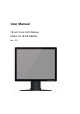
1. Application This high-resolution color display with touch screen use is specifically designed to meet the rigorous performance standards needed for diagnostic, interventional radiology, and other medical applications. To guarantee image integrity, features include accurate signal conversion and a wide range of interfacing options. Compact design -Low weight and small size with improved performance make the color flat panel display HL1916S SERIAL preferable to conventional CRT monitors.
2. Declarations Safety precautions Medical Equipment With respect to electric shock, Fire and mechanical hazards only in accordance with ANSI/AAMI ES60601-1:2005&CSA C22.2 No.60601-1:2008 WARNING: To avoid risk of electric shock, this equipment must only be connected to a supply mains with protective earth. Appliance coupler or separable plug of is used as isolation means to isolate the equipment from mains supply.
Do not insert any objects into the housing Objects inserted into the housing may result in damage to the unit or personal injury. Do not place any objects on top of the units Penetrating liquids may result in a fire or electric shock. Connection No contact to a patient must occur when handling the cables. Do not hurt yourself, when moving the display The display can be tilted backwards and forwards. Please, pay attention not to hurt yourself, when moving the display.
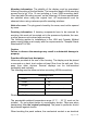
Mounting information: The stability of the display must be guaranteed following mounting of the foot/holder. The immersion depth of the mounting screws has to be 10 to 12 mm including a 3 mm VESA mounting plate. (See also table "Mounting screws" on the following). All these requirements are satisfied when using the original foot. All requirements must be observed when using customer-specific mounting solutions. Notice for users: The plug panel closed by the cover, must not be opened by users.
discharge may cause a brief disturbance in the picture quality. Care of unit / cleaning agents − The front panel is extremely sensitive to mechanical damage. Avoid all scratches, knocks etc.! − Remove water drops immediately; extended contact with water discolors the surface. Clean the front panel when dirty,using a micro fiber cloth and, if necessary, a glass cleaning agent. Only clean housing parts using a cleaning agent for plastics. z Note: Do not use cleaning agents containing solvent, e.g.
screen. Minimize mirroring In order to reduce mirroring on the unit, ceiling lighting or reflected light (no dazzling) should be used. Mirroring can only be eliminated if the screen is clean and free of grease. Clean the display using a suitable micro fiber cloth. Change of environment If the unit is brought into a warm environment from a cold one, water may condense upon it. The unit should not be switched on until all the condensed water has evaporated, including that inside the unit.
Use a power cable with PE conductor corresponding to the safety requirements of the respective country of use. Note for North America: Molded power supply plugs must comply with the requirements for hospitals with respect to CSA Std. C22.2 No. 21 and UL 498.The power supply and signal connections are located on the rear of the color flat panel display. Note Note that the cables are already positioned when you receive the display (power cable and DVI-D cable).
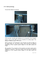
4.1.2 Cable (attaching) Connect the cables to the display. VGA connector: the flat panel display can be connected to the computer system using a VGA Cable on D-sub connection for analog signal. The display is adapted using an OSD menu. DVI-D connection: The connection to the computer can also be made via the digital single link. The picture quality, noise immunity and radiated interference of the complete system depend on the cable quality and length.
Serial connection: you can connect the display via the RJ11 connector to the computer for firmware updating. 4.1.3 Stand base (attaching) Put the stand base near VESA holes of the monitor. Fasten the stand base with four M4x12 screws. Move the button of stand base towards the right, and lift the monitor, and then turn the monitor by 90 degrees. Button of stand base Note: the stand base is optional. 4.1.4 Mounting Use Remove the stand base according to the contrary way in 4.1.3.
mount by mounting screws (see page 6 table Mounting Screws for details). 4.2 Switching on the display Switch on the flat panel display using the power switch. The operation LED lights up (color: green, provided the timing has been recognized – please refer to section 7 "Fault diagnostics"). 4.3 Adjusting the image geometry The display automatically recognizes the used standard, and set-up values for each standard are preprogrammed.
− Adjust the brightness so that image sections with 5% and 0% blackness still visibly contrast from one another. − Adjust the contrast so that image sections with 95% and 100% whiteness still visibly contrast from one another. To adapt the luminosity to the ambient lighting, adjust the backlight brightness (note: 180 cd/m² factory setting is then modified). 4.5 Screen saver A screen saver function should be used in order to reduce "image sticking" which can occur in TFT displays.
5.3 Information on additional serial interface (Service Only) Serial connection: you can connect the display via the RJ11 connector to the computer for firmware updating and monitor test. 5.4 Analog and digital inputs (DVI,VGA,DP) DVI socket With DVI digital signal through DVI cable. VGA socket Use VGA cable for VGA input. DP socket With DP digital signal through DP cable. 5.5 Power supply connection Note Device fuses can not be exchanged outside of the repair centers.
5.6 Serial interface Caution No other units may be connected to the service socket. Connection or disconnection of a unit may only be carried out by servicing personnel or those trained by them. A Serial Spot Meter or Universal Serial Luminance Meter must not be connected in the presence of patients. The display has a serial RS 232 4 pins RJ11 interface sockets to update the SW. 6. Adjustments 6.
brightness and contrast levels for and only for analog inputs. Note that the calibration (in the Look Up Table) is not changed by these adjustments (All the monitors are and remain factory calibrated): Using a 100% black picture and an appropriate measurement device (a spot meter recommended), decrease the brightness level using the OSD controls until the measurement device displays a constant level (i.e. the measured value no longer changes).
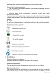
6.3 OSD menu 6.3.1 Keys assignment and operation LED Menu Up Down Set A “dynamic help for keypad function” is available for each menu: it explains the role of each key depending on the OSD menu window, which is currently active. 6.3.2 Key functions without active OSD menu Key Action Menu Activate OSD Up Define VGA port Down Select DVI-D,DP, VGA input source Note: While there is no sync in VGA input, there is instruction on the OSD to indicate that how to define the analog input as VGA input.
6.3.3Key functions in the OSD menu Key(s) Situation Action Menu Always Jump to next line Up Slide controller Increase value Command "Enter key" Down Slide controller Decrease value Set Sub-menu Return to previous menu 6.3.4 Menu calls Press the “Menu” key while the OSD is active, the function icon will jump to next line. Pressing the “Up” key, the coordinate submenu will be selected. Press “Set” key to return to the main menu while in the submenu state. 6.3.
Display Settings Contrast 0…100 Backlight 0…100 Color Color1 Color2 Color3 User R G B Gain R G B Bias 0…255 H Position (Analog only) V Position (Analog only) Shift picture in horizontal direction 0…255 Shift picture in vertical direction Frequency (Analog only) 0…100 Adjust the frequency and phase of the input signal.
(Analog only) with the monitor Auto-Configure ON / OFF Execute OSD Settings Information Service Level 2 Exit Horizontal position Vertical position 0 … 255 0 … 255 Background 0 … 12 LED ON/OFF Language English 中文 Automatically adjust the image display settings. The selected auto functions are executed. Note: The quality of the function depends on the applied picture contents. To get better effect it is recommended to apply full screen picture and including white and dark contents.
7.
8. Technical data All technical data are valid after a warming-up period of 2 hours. 8.1 Display Type TFT, color active matrix Display area 376.32m x 301.06 mm Picture diagonal 19" or 48 cm Native resolution 1280 x 1024 (full-screen format) Pixel organization 3 vertical sub pixels Pixel pitch 0.294 mm x 0.
color depth for color images - will also be reduced and might be visible) Timing recognition H frequency, V frequency 8.4 Inputs/outputs 8.4.1 Analog signal input VGA input Via VGA socket, single link 8.4.2 Digital signal input DVI-D input Via DVI socket , single link DP input Via DP socket DDC Via DVI 8.4.3 Serial interface RS232 Via RJ11 connector 8.4.
Sync level: 0.2---0.3V DVI-Digital Single link DVI Digital TMDS: 600mV for each differential line Input Impedance: 50 ohm DVI EDID datum Display Port EDID via DVI I2C bus Display Port 1.1 Receiver 4 main Lanes Display Port: 600mV for each differential line Impedance: 100 ohm per differential pair DP EDID datum EDID via AUX channel 8.
Ambient temperature range +5 -- +35℃ Temperature gradient Max. 7℃/h , no condensation Relative Humidity 15%-85% Atmospheric pressure 70 – 106 kPa Transport and storage (packed) Ambient temperature range -20 -- +60℃ Temperature gradient Max. 10℃/h, no condensation Relative Humidity 10%-90% Atmospheric pressure 70 – 106 kPa 8.8 Mechanical requirements Operation Vibration According to EN 60068-2-6 10 ... 58 Hz with ± 0.075 mm deflection 58 ...
Conformity GAMMA2.2 8.10 Electromagnetic compatibility IEC60601-1-2 Class B FCC Part15 class B 9. Dimensional drawings All dimensions in mm. 9.
10 Remarks and contact address Invalidity of guarantee All unauthorized electrical or mechanical alterations on or in the unit result in loss of the guarantee. Information on the Instruction Manual For clarity reasons, this Instruction Manual does not contain all detailed information on this product. Your attention is additionally drawn to the fact that the contents of this Instruction Manual are not part of a previous or existing agreement, commitment or statutory right and do not change the latter.
part 15 of the FCC Rules. These limits are designed to provide reasonable protection against harmful interference in a residential installation. This equipment generates, uses and can radiate radio frequency energy and, if not installed and used in accordance with the instructions, may cause harmful interference to radio communications. However, there is no guarantee that interference will not occur in a particular installation.