
User's Manual
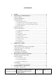
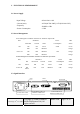
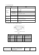
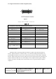
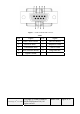
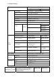
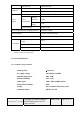
Table Of Contents
- Customer Specification
- HL1916
- 1. SCOPE
- 2. ELECTRICAL PERFORMANCE
- 2.1 Power Supply
- 2.2 Power Management
- 2.3 Signal Interface
- 2.3.1 Signal Specifications
- 2.3.2 D-SUB Connector and Pin Assignment (Figure1)
- 2.3.3 Digital Visual Interface and Pin Assignment (DVI)
- 2.3.4 Control Interface
- 2.4 Product Features
- 2.5 Screen Performance
- 2.5.1 Standard Testing Conditions
- 2.5.2 Brightness
- 2.5.3 View angle
- 2.5.4 Brightness Uniformity
- 2.5.5 Contrast radio
- 2.5.6 White Color Coordinates
- 2.5.7 Response Time
- 2.5.8 Color Gray
- 2.5.9 Gamma Curve
- 3. OPERATING GUIDE
- 4. MECHANICAL SPECIFICATIONS
- 5. ENVIRONMENT CONDITONS
- 6. DEFECT, SCRATCH and DUST
- 7. NOTICE FOR HANDING
- Appendix 1 Preset Timings

2.3.1 Signal Specifications
Item SPEC
Frequency
Analog:
H 30 ~ 82kHz
V 50 ~ 85Hz
Pixel clock 25--165MHz
Video Input
Analog 0.7Vpp
Input Impedance 75 Ohm
Signal Input
(Analog)
D-SUB
Signal Input Separate Sync, TTL (N or P)
CVS Signal
Video Level: 0.5---1.0V
Sync level: 0.2---0.3V
DVI-I Input Via DVI-I to VGA connector
DVI-D Input
DVI-Digital
DDC via DVI
2.3.2 D-SUB Connector and Pin Assignment (Figure1)
Figure 1
15-pin Min D-type Female Connector
Table 1
Pin - Assignment of 15-pin D-sub:
1 Red Video 6 Red Ground 11 Monitor Ground
2 Green Video 7 Green Ground 12 DDC-Serial Data
3 Blue Video 8 Blue Ground 13 H-Sync.
4 N/C 9 NC 14 V-Sync.
5 GND 10 Logic Ground 15 DDC-Serial Clock
Last change: 27
th
, Oct. 2005
Copyright @ SSME (SIEMENS
Medical Equipment Ltd.) All
rights reserved
HL1916
Page 6 of 32