
User's Manual
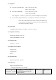
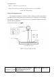
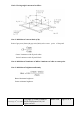
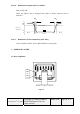
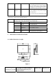
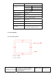
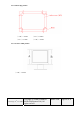
Table Of Contents
- Customer Specification
- HL1916
- 1. SCOPE
- 2. ELECTRICAL PERFORMANCE
- 2.1 Power Supply
- 2.2 Power Management
- 2.3 Signal Interface
- 2.3.1 Signal Specifications
- 2.3.2 D-SUB Connector and Pin Assignment (Figure1)
- 2.3.3 Digital Visual Interface and Pin Assignment (DVI)
- 2.3.4 Control Interface
- 2.4 Product Features
- 2.5 Screen Performance
- 2.5.1 Standard Testing Conditions
- 2.5.2 Brightness
- 2.5.3 View angle
- 2.5.4 Brightness Uniformity
- 2.5.5 Contrast radio
- 2.5.6 White Color Coordinates
- 2.5.7 Response Time
- 2.5.8 Color Gray
- 2.5.9 Gamma Curve
- 3. OPERATING GUIDE
- 4. MECHANICAL SPECIFICATIONS
- 5. ENVIRONMENT CONDITONS
- 6. DEFECT, SCRATCH and DUST
- 7. NOTICE FOR HANDING
- Appendix 1 Preset Timings

Note 6: Definition of response time is as follows:
Sum of TrD, TfR
When the display data is changed from white to black, response time is
measured
100
90
10
0
%
Optical
Response
white
black
white
Tr
D
Tr
R
Note 7: Definition of Color Chromaticity (CIE 1931)
Color coordinate of Red , Green, Blue & White at center point .
3. OPERATING GUIDE
3.1 Keys assignment
DOWN
UP
MENU
LED
SET
Figure 4
Last change: 27
th
, Oct. 2005
Copyright @ SSME (SIEMENS
Medical Equipment Ltd.) All
rights reserved
HL1916
Page 14 of 32