User Manual 19 inch LCD Monitor for Medical Ver.
Change History Version Date 00 Review June 15, 2013 Last change: 17th Jun, 2013 Author User Manual Modification Wangyang Preliminary Release DSC1913-D/DC Page 2 of 33
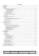
Contents 1. Application........................................................................................................................................................................4 2. Declarations....................................................................................................................................................................5 3. Installation ..........................................................................................................................
1. Application This high-resolution color display is specifically designed to meet the rigorous performance standards needed for diagnostic, interventional radiology, and other medical applications. To guarantee image integrity, features include accurate signal conversion and a wide range of interfacing options. Compact design -Low weight and small size with improved performance make the color flat panel display DSC1913-D preferable to conventional CRT monitors.
2. Declarations Safety precautions Medical Equipment With respect to electric shock, Fire and mechanical hazards only in accordance with UL 60601-1 and CAN/CSA C22.2 No. 601.1 WARNING: To avoid risk of electric shock, this equipment must only be connected to a supply mains with protective earth. APPLIANCE COUPLER or separable plug of is used as isolation means to isolate the equipment from mains supply.
Danger: There is a danger to life if the warning information is not observed. Severe personal injury or damage to property may occur. Do not open the unit yourself. Certain components inside the units are at high-voltage, i.e. touching these components presents a danger to life! Only use a perfect power supply cable A damaged power supply cable may result in a fire or electric shock. When disconnecting the power supply cable, always do so by holding the plug.
- Use of a safety transformer - Use of additional PE conductor Only use the signal cables and interface cables specified by the manufacturer for the installation. Use power cables with a PE contact. Only insert into sockets with a PE contact. For certain applications, the video earth can be separately connected to the PE via the additional PE connection in the plug panel (observe IEC 601-1-1). Close the plug panel using the provided cover , and secure using the screws.
Mounting screws Number 4 Thread M4 Strength 12 Min. 10 mm; Max. 12 mm Max. 3 Nm Immersion depth Torque Please see 4.1.4 for details. The permissible ambient temperature range (5 °C ... 35 °C) must not be violated. Do not subject device to unnecessary shocks. Take care when transporting! Use the original p ackaging! The panel in particular should be protected against shocks.
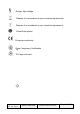
Danger, high voltage Dispose of in accordance to your countries requirements Dispose of in accordance to your countries requirements China Rohs symbol European comformity China Compulsory Certification Hg TUV approval mark Last change: 17th Jun, 2013 User Manual DSC1913-D/DC Page 9 of 33
3. Installation Provide adequate ventilation Ventilation slots are located on the rear of the housing. Ambient temperature The permissible ambient temperature range must not be violated. Minimize reflections The display should be positioned so that reflections of lights, windows, furniture with shiny surfaces or light-colored walls do not appear on the screen. Minimize mirroring In order to reduce mirroring on the unit, ceiling lighting or reflected light (no dazzling) should be used.
4. Start-up Caution In order to ensure safe operation of the equipment, close attention must be paid to the information contained in this Instruction Manual as well as the warnings in Section 2 "Safety precautions". Caution Information for end customer None of the settings must be changed on site by the user, otherwise the guarantee is canceled. This also applies to settings made using the DSC1913-D keys. These are therefore locked for certain applications.
4.1.1 Little cover (removing) Remove the one screws with a M4 Slot screwdriver (one turn suffices). Open the little cover and remove it 4.1.2 Cable (attaching) Connect the cables to the display.
DVI-A connector: the flat panel display can be connected to the computer system using a VGA-DVI-A Cable on the analog channel of a DVI connection for analog signal. The display is adapted using an OSD menu. BNC connector: the flat panel display can be connected to the video camera using a BNC-DVI-A Cable for analog signal. The display is adapted using an OSD menu. DVI-D connection: The connection to the computer can also be made via the digital single link.
Put the stand base inside the monitor. Fasten the stand base with four M4x12 screws. 4.1.4 Mounting Use Remove the stand base and put on the cover according to the contrary way in 4.1.3. Remove the four screws at the VESA holes, and then fixed the mount by mounting screws (see page 6 table Mounting Screws for details). 4.2 Switching on the display Switch on the flat panel display using the power switch.
to section 7 "Fault diagnostics"). 4.3 Adjusting the image geometry The display automatically recognizes the used standard, and set-up values for each standard are preprogrammed. However, depending on the graphics card used, it may still be necessary to align and size the picture for the selected standard (see Section 6.1 "Picture adjustment"). Normally auto adjust will work. 4.
5. Connections 5.1 Connecting the flat panel display Note All screening precautions contained in the corresponding EMC guidelines must be observed. If these guidelines are not observed, interference signals could penetrate the monitor. Information on cable installation Only screened cables are permitted for the signal connections. All connectors should be of screw or locking types (as far as possible). Signal and power cables must not be routed in the same duct.
5.4 Analog and digital inputs (DVI-I, DP, BNC) DVI-I connector Connect VGA-DVI-A cable with DVI-I connector (male) for the analog input to the DVI- connector (female). Or connect DVI-D cable for digital signal. DP socket With DP digital signal through DP cable. BNC connector Use BNC-DVI-A cable (optional) for BNC input. 5.5 Power supply connection Note Device fuses can not be exchanged outside of the repair centers. The display power supply is connected using an appliance plug.
The maximum current is 1A. Connection or disconnection of a unit may only be carried out by servicing personnel or those trained by them. 6. Adjustments 6.1 Picture adjustment This section describes the settings for operation of the flat panel display with a video source. The most important settings are: Adjusting the graphics memory of the video source As with all monitors, the flat panel display also has certain limits, e.g. maximum resolution and vertical frequency.
meter recommended), decrease the brightness level using the OSD controls until the measurement device displays a constant level (i.e. the measured value no longer changes). Once this is achieved, increase the brightness level slightly until the display is just above the absolute lowest black level (one step is generally sufficient). Similarly, set the white level using a 100%-white test pattern and the measurement device.
6.3 OSD menu 6.3.1 Keys assignment and operation LED Menu Up Down Set LED A “dynamic help for keypad function” is available for each menu: it explains the role of each key depending on the OSD menu window, which is currently active. 6.3.
The ‘Down’ key function is used to select input source and is enabled only when OSD menu is locked. This function can be enabled or disabled through OSD selection. This choice is in case all the signal sources are available. If not, the monitor will auto search DVI-D, DP and VGA (or BNC depended on which one is defined). 6.3.
6.4 Description of the menus Main Menu Performance Display Settings Last change: 17th Jun, 2013 Function Brightness Adjustment range 0…100 Contrast 0…100 Backlight 0…255 Color Color1 Color2 Color3 User R G B Gain R G B Bias 0…255 H Position (Analog only) V Position (Analog only) 0…255 Description Set brightness. Adapting the image quality of darker picture areas. The center point is in 50 position. Note: The brightness settings are already optimized for digital signals.
PhaseG (Analog only) PhaseB (Analog only) Sharpness Input Source Auto Adjust (Analog only) Last change: 17th Jun, 2013 G ADC clock phase 0…7 B ADC clock phase 0…7 Interpolation filter -5 to 5 DVI-D DP VGA BNC One of the 11 filters can be selected for the sharpness setting to reduce scaling artifacts. Interpolation filters depend on the input resolution. Digital signals which is used with 1280X1024 resolution can not be adjusted since each pixel is controlled by its own pulse.
Execute OSD Settings The selected auto functions are executed. Note: The quality of the function depends on the applied picture contents. To get better effect it is recommended to apply full screen picture and including white and dark contents. Horizontal position Vertical position 0 … 255 0 … 255 Background 0 … 12 LED ON/OFF Language English 中文 Adjustment of OSD horizontal position Adjustment of OSD vertical position Select the OSD background transparency Setting the status of the operation LED.
7. Fault diagnostics Fault No picture appears on the display, operation LED off No picture appears on the display, operation LED green blinking Fuzzy picture, interference in vertical lines Other faults –LED orange blinking Other faults: “Temp.
8. Technical data All technical data are valid after a warming-up period of 2 hours. 8.1 Display Type Display area Picture diagonal Native resolution Pixel organization Pixel pitch Contrast ratio Horizontal viewing angle Vertical viewing angle Backlight Brightness 6 dual CCFT (cold cathode fluorescent tube) Typically 280 cd/m² Factory setting: 137 cd/m² Lifetime backlight 50,000 hours typically for CCFT (applies to an ambient temperature for the backlight of 25°C) of TFT, color active matrix 376.
8.3 Electronics Multi-standard technology Timing recognition Video modes with resolutions less than 1280 x 1024 can be expanded to the TFT resolution, and thus utilize the full display area (like multi-sync CRTs). In the same way, resolutions higher than 1280 x 1024 can be reduced and then displayed.
8.4.4 Timing Input Item Analog VGA Frequency Horizontal: 31 ~ 82kHz Vertical: 56 ~ 75Hz Pixel clock 25—140 MHz Video Bandwidth ≥ 165M Hz Video Input Analog 0.7Vpp Input Impedance: 75 Ohm Sync Signal Input Separate Sync, Composite Sync on Hs, TTL/LVTTL (N or P) VGA EDID datum SOG CVS Signal DVI Digital Display Port Via DVI-I analog channel EDID via DVI I²C bus Analog R,G, B: 0.7Vpp Input Impedance: 75 Ohm Sync on Green: 0.2-0.
8.5 Controls and connection elements Front Side Rear Four keys for OSD menu, operation-LED • Power switch •Power supply connection • DVI socket • DP socket • RS 232 sockets RJ11 • DC 5V/1A 8.6 Mechanical design Item Last change: 17th Jun, 2013 Set Width 419.6mm Depth 212mm Height 406.6~466.6 mm Tilt -5 degree ~15 degree Housing components Plastic Kensington lock On the rear of stand base Visible surface Approx.
8.7 Climatic conditions Operation Ambient temperature range Temperature gradient Relative Humidity Atmospheric pressure +5 -- +35℃ Max. 7℃/h , no condensation 15%-85% 70 – 106 kPa Transport and storage (packed) Ambient temperature range Temperature gradient Relative Humidity Atmospheric pressure -20 -- +50℃ Max. 10℃/h, no condensation 10%-90% 70 – 106 kPa 8.8 Mechanical requirements Operation Vibration Shock According to EN 60068-2-6 10 ... 58 Hz with ± 0.075 mm deflection 58 ...
8.9 Safety specifications Safety standards Approvals Protection class Degree of protection to DIN 40050 Type B/BF/CF applied part Category AP/APG equipment Conformity EN 60601, IEC 601 UL 60601-1:2003 R6.03 / CAN/CSA-C22.2 No.601.1-M90 service: cTUVus certificate CCC, CB (NCB Lab.) Protection class I IP 20 No Applied Part No AP/APG CE 8.
9. Dimensional drawings All dimensions in mm. 9.
10 Remarks and contact address Invalidity of guarantee All unauthorized electrical or mechanical alterations on or in the unit result in loss of the guarantee. Information on the Instruction Manual For clarity reasons, this Instruction Manual does not contain all detailed information on this product. Your attention is additionally drawn to the fact that the contents of this Instruction Manual are not part of a previous or existing agreement, commitment or statutory right and do not change the latter.
FCC Statement: This device complies with part 15 of the FCC Rules. Operation is subject to the following two conditions: (1) This device may not cause harmful interference, and (2) this device must accept any interference received, including interference that may cause undesired operation. This equipment has been tested and found to comply with the limits for a Class B digital device, pursuant to part 15 of the FCC Rules.