User Manual 19 inch LCD Monitor for Medical HL1928M-L/R Ver.
Contents 1. Application........................................................................................................................................................................3 2. Declarations ......................................................................................................................................................................4 3. Installation........................................................................................................................
1. Application This high-resolution color display is specifically designed to meet the rigorous performance standards needed for diagnostic, interventional radiology, and other medical applications. To guarantee image integrity, features include accurate signal conversion and a wide range of interfacing options. Compact design -Low weight and small size with improved performance make the monochrome flat panel display HL1928M preferable to conventional CRT monitors.
2. Declarations Safety precautions Medical Equipment With respect to electric shock, Fire and mechanical hazards only in accordance with UL 60601-1 and CAN/CSA C22.2 No. 601.1 WARNING: To avoid risk of electric shock, this equipment must only be connected to a supply mains with protective earth. APPLIANCE COUPLER or separable plug of is used as isolation means to isolate the equipment from mains supply.
Danger: There is a danger to life if the warning information is not observed. Severe personal injury or damage to property may occur. Do not open the unit yourself. Certain components inside the units are at high-voltage, i.e. touching these components presents a danger to life! Only use a perfect power supply cable A damaged power supply cable may result in a fire or electric shock. When disconnecting the power supply cable, always do so by holding the plug.
Installation should be carried out by trained personnel When installing your medical electrical system with our products in an environment with patients, please observe the safety requirements of EN 60601-1-1 (IEC 601-1-1) for "Specifications for the safety of medical electrical systems" in order to prevent injury to patients and users of your systems. For certain applications, the video earth can be separately connected to the PE via the additional PE connection in the plug panel (observe IEC 601-1-1).
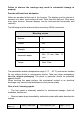
Failure to observe the warnings may result in substantial damage to property. Provide sufficient heat dissipation Holes are provided at the rear of the housing. The display must be placed or secured on a hard, level surface at least 10cm from the wall and 15cm away from other devices. Several displays can be butt-mounted horizontally and vertically. The following must be observed when mounting (VESA connection): Mounting screws Number 4 Thread M4 Strength 12 Immersion depth Min. 10 mm; Max.
Clean the front panel when dirty, using a micro fiber cloth and, if necessary, a glass cleaning agent. Only clean housing parts using a cleaning agent for plastics. Note: Do not use cleaning agents containing solvent, e.g.
nervous system and is toxic in high doses. Lamp Disposal Hg Lamp(s) inside this product contains mercury and must be recycled or disposed of according to state, local or federal law. For more information, Contact the electronic industries alliance at www.Elae.org. For lamp specific disposal information check www.lamprecycle.org. 3. Installation Provide adequate ventilation Ventilation slots are located on the rear of the housing.
In order to ensure safe operation of the equipment, close attention must be paid to the information contained in this Instruction Manual as well as the warnings in Section 2 "Safety precautions". Caution Information for end customer None of the settings must be changed on site by the user, otherwise the guarantee is canceled. This also applies to settings made using the HL1928 M keys. These are therefore locked for certain applications.
4.1.2 Cable (attaching) Connect the cables to the display. VGA connector: the flat panel display can be connected to the computer system using a VGA Cable. The display is adapted using an OSD menu. BNC connector: the flat panel display can be connected to the video camera using a BNC Cable . The display is adapted using an OSD menu. DVI connection: The connection to the computer can also be made via the digital single link.
4.1.3 Little cover (attaching) Lead the monitor end of the cables through the little cover’s cable duct. Connect the little cover to the rear cover. 4.2 Power up the display Power up the display and the operation LED lights up (color: green, provided the timing has been recognized – please refer to section 7 "Fault diagnostics"). 4.3 Adjusting the image geometry The display automatically recognizes the used standard, and set-up values for each standard are preprogrammed.
− Adjust the contrast so that image sections with 95% and 100% whiteness still visibly contrast from one another. To adapt the luminosity to the ambient lighting, adjust the backlight brightness (note: 500 cd/m² factory setting is then modified). 4.5 Screen saver A screen saver function should be used in order to reduce "image sticking" which can occur in TFT displays. It is high risk to display a static graphic over half an hour.
5. Connections 5.1 Connecting the flat panel display Note All screening precautions contained in the corresponding EMC guidelines must be observed. If these guidelines are not observed, interference signals could penetrate the monitor. Information on cable installation Only screened cables are permitted for the signal connections. All connectors should be of screw or locking types (as far as possible). Signal and power cables must not be routed in the same duct.
5.4 Analog and digital inputs (DVI,VGA, BNC) DVI socket With DVI digital signal through DVI cable. VGA socket With VGA cable for VGA input. BNC connector Use BNC cable (optional) for BNC input. 5.5 Power supply connection Note Device fuses can not be exchanged outside of the repair centers. The display power supply is connected using an appliance plug. Only use the power cable supplied in the delivery, or a cable with PE conductor and appliance socket to DIN 49 547, IEC 320.
Caution A power cable with PE conductor must be used which corresponds to the safety requirements of the respective country of use. 5.6 Serial interface Caution No other units may be connected to the service socket. Connection or disconnection of a unit may only be carried out by servicing personnel or those trained by them. A Serial Spot Meter or Universal Serial Luminance Meter must not be connected in the presence of patients. The display has a serial RS 232 DIN6 interface sockets to update the SW. 6.
Fine adjustment of the flat panel display Note Fine adjustment of the flat panel display can only be carried out via the analog port. The digital input (DVI-D,) does not require a fine adjustment since the display signal is always optimum. RGB picture sources via VGA connector supply analog signals which are basically intended for conventional CRT monitors and which are processed directly by them.
slightly (1 or 2 steps is generally sufficient). At this point, the display is configured for optimal performance with the installed graphic board. If one is not yet satisfied with the luminance level, the black and white levels can be further increased by adjusting the backlight level in the OSD menu. Please note that higher backlight level settings tend to reduce the stability of luminance over time. 6.
role of each key depending on the OSD menu window, which is currently active. 6.3.2Key Functions without active OSD Menu Key Action Menu Activate OSD 6.3.3Key Functions in the OSD Menu Keys Situation Action Menu Always Jump to next line Up Slide controller Increase Value Command “Enter Key” Down Slide controller Decrease value SET Always Exit current menu (Settings are retained) 6.3.4Submenu Calls Press the “Menu” key while the OSD is active, the function icon will jump to next line.
Image Brightness 0…255 Adjustment brightness of LCD backlight to adapt total brightness for room illumination. Contrast 0…255 (Default=128) Adjustment of contrast This allows the brighter area to be seen more distinctly. The center point is in 128 position. 0…255 (Default=128) Black level 0…48 (Default=5) Sharpness Reset Last change: 2012-3-1 User Manual It is used to adjust the black level of the monitor. The center point is in 128 position.