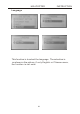
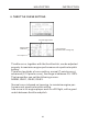
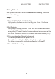
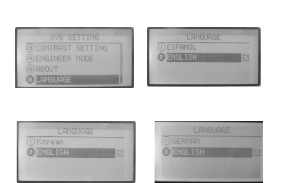
HELICOPTER INSTRUCTION Language This function is to select the language. The selection is as shown in the picture , if only English or Chinese menu , the function is not exist .
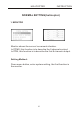
HELICOPTER INSTRUCTION NORMAL SETTING(helicopter) 1. MONITOR Monitor shows the servos’ movement situation. In PCMS, this function is to describe the 9 channels output. In PPM, this function is to describe the first 8 channels output. Setting Method: Press menu button, enter system setting, the first function is the monitor.
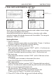
HELICOPTER INSTRUCTION 2. DUAL RATE & EXPONENTIAL SETTING (1). AIL Servo Switch Curve picture (please refer to Page 27) Dual rate Exponential Curve point (3). RUD (2). ELE Dual rate is to adjust aileron, elevator and rudder travel range. The range is between 0%-120%. Exponential setting is to adjust aileron, elevator and rudder sensitivity when the sticks are around the middle. The range is between -100% to +100%. Setting Method: 1. Select channel Aileron, elevator and rudder are selectable.
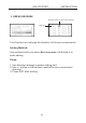
HELICOPTER INSTRUCTION 3. SERVO REVERSE Direction (Rev-reverse, Nor-normal) Channel This function is to change the direction of the servos movement. Setting Method: Use up/down button to select Servo reverse, OK button is to enter editing. Steps: 1. Use direction buttons to select editing part. 2. Use +/- button or OK button to switch the servo movement direction. 3. Press EXIT after setting.
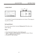
HELICOPTER INSTRUCTION 4. END POINT Channel Side Value It is to adjust the end of individual servo’s travel. The range is from 0% to 120%. Setting Method: Use up or down button to select End point, OK button is to enter editing. Steps: 1. Use direction buttons to select editing part. 2. Use +/- button or OK button to set the travel value. Press OK for a while backs to default. 3. Press EXIT after setting.
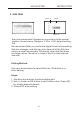
HELICOPTER INSTRUCTION 5. SUB TRIM Channel Value High/Low Sub trim makes small changes or corrections to the neutral position of each servo. Range is -120 to +120, default setting is 0. We recommend that you center the digital trims before making Sub trim changes, and that you tryto keep all of the Sub trim values as small as possible. Otherwise, when the Sub trims are large values, the servo’s range of travel is restricted on one side.
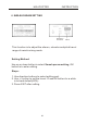
HELICOPTER INSTRUCTION 6. SWASH PARAM SETTING Effection direction Value This function is to adjust the aileron, elevator and pitch travel range of swash mixing mode. Setting Method: Use up or down button to select Swash param setting, OK button is to enter editing. Steps: 1. Use direction buttons to select editing part. 2. Use +/- button to set the travel. Press OK button for a while is to back default(60%). 3. Press EXIT after setting.
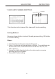
HELICOPTER INSTRUCTION 7. AUXILIARY CHANNELS SETTING Channel Switch Direction This function is for channel 5 to channel 9 function setting. Setting Method: Use up or down button to select Swash param setting, OK button is to enter editing. Steps: 1. Use direction buttons to select editing part. 2. Use +/- button to set the switches or knobs. The switches can be set from A to F, the knobs can be set as VA, VB, VC, VL, VR or none(-). 3.
HELICOPTER INSTRUCTION 8. THROTTLE CURVE SETTING Current flight mode Flight mode Dual rate Curve picture (Please refer to Page 27) Curve point Throttle curve, together with the throttle stick, can be adjusted properly to maximize engine performance at a particular pitch setting. There are two kinds of curve setting, normal (7 points curve), advanced (2-10 points curve), the range is between 0%-120%. The transmitter can set the following curves: NORM, IDLE1, IDLE2, IDLE3.
HELICOPTER INSTRUCTION Setting Method: Use up/down button to select Throttle curve setting, OK button is to enter editing. Steps: 1. Flight(NORM IDLE1 IDLE2 IDLE3) Use direction buttons to select editing part. Use +/- button to select one curve. 2. Set Dual rate Use direction button to select “D/R” and edit (one or two values can be set separately or together). Press +/- button for seconds can increase or delete the value. Press OK button for seconds is to back default(60%). 3.
HELICOPTER INSTRUCTION 9. PITCH CURVE SETTING Flight mode Dual rate Curve picture (Please refer to Page 27) Curve point Pitch curve, together with the throttle stick, can be adjusted properly to maximize engine performance at a particular pitch setting. There are two kinds of curve setting, normal (7 points curve), advanced (2-10 points curve), the range is between 0%-120%. The transmitter can set the following curves: NORM, IDLE1, IDLE2, IDLE3.
HELICOPTER INSTRUCTION Setting Method: Use up/down button to select PITCH CURVE SETTING, OK button is to enter editing. Steps: 1. Flight(NORM IDLE1 IDLE2 IDLE3) Use direction buttons to select editing part. Use +/- button to select one curve. 2. Set Dual rate Use direction button to select “D/R” and edit (one or two values can be set separately or together). Press +/- button for seconds can increase or delete the value. Press OK button for seconds is to back default(60%). 3.
HELICOPTER INSTRUCTION 10. REVOLUTION MIXING This curve mix adds opposite rudder input to counteract the changes in torque when the speed and collective pitch of the blades is changed. Setting Method: Use up/down button to select Revolution mixing, OK button is to enter editing. Steps: 1. Flight(NORM IDLE1 IDLE2 IDLE3) Use direction buttons to select editing part. Use +/- button to select one curve. 2.
HELICOPTER INSTRUCTION 11. TRIM STEP SETTING This function is to change the rate at which the trim moves when the TRIM LEVER is activated. The range is from1to 250. Generally larger trim steps are for models with larger control throws or for first flights to ensure sufficient trim to properly correct the model. Smaller trim steps are later used to allow very fine adjustments in flight. Setting Method: Use up/down button to select Trim step setting, OK button is to enter editing. Steps: 1.
HELICOPTER INSTRUCTION 12. THROTTLE CUT SETTING This function is to shut off the engine at the end of a flight. The engine can be stopped with one touch of any switch, eliminating the need to move the trim to kill the engine and then readjust prior to each flight. The helicopter THR CUT includes an ON/OFF throttle position (normally a little above idle). You must move the THROTTLE STICK back below the set point before the THR-CUT function can be reset, to avoid sudden engine acceleration.
HELICOPTER INSTRUCTION 13. FLY MODEL SWITCH Fly mode Switch Fly mode statue This function is to select the flight mode. Setting Method: Use up/down button to select Fly model switch, OK button is to enter editing. Steps: 1. Use direction buttons to select editing part. 2. Use +/- button to set every fly model. 3. Use +/- button to set fly model ON/OFF position. 4. Press EXIT after setting.
HELICOPTER INSTRUCTION 14. THROTTLE HOLDING SETTING This function can make the throttle servo operating at a low speed position at the end of a flight. The range is between -75% and +75%. User can set the mix function with rudder under the throttle holding state and the mix rate (offset). This function switch can be found in “Fly model switch”. Setting Method: Use up/down button to select Throttle holding setting, OK button is to enter editing. Steps: 1. Use direction buttons to select editing part. 2.
HELICOPTER INSTRUCTION 15. FAIL SAFE This function is to set responses in case of loss of signal or low RX battery. Setting Method: Use up/down button to select Fail safe, OK button is to enter editing. Steps: 1. Use direction buttons to select editing part. 2. Use +/- button to select “hold” or “0.0%” 3. Press OK button to confirm the current parameter. 4. Press EXIT after setting.
HELICOPTER INSTRUCTION 16. TIMER The flight time of every helicopter is different according to the different tank of fuel, engine, ESC, etc. Timer function can alarm you to land before the fuel lacks. The transmitter can set 3 timers (A, B, C). The longest time can be set as MM99SS59. The countdown timer can alarm user before 10 minutes. The alarm will become 2S/1S from 1S/1S in the last 10 seconds. When the countdown timer is 0, the time will add up. The timer can be seen in the opening screen.
HELICOPTER INSTRUCTION 17. ADVANCED To realize an idea fly, there are 21 advanced function in ADVANCED. Setting Method: Use up/down button to select ADVANCED, OK button is to enter editing. +/- button can turn page. About each advanced functions please read the following pages.
HELICOPTER INSTRUCTION ADVANCED FUNCTION INTRODUCTION (1). GYRO SENS SETTING User can adjust the gyro sensitivity by transmitter, AVCS gyro (GY) and normal gyro (STD). Gyro sensitivity switch plug should plug in the fifth channel of receiver. The auxiliary channel CH 5 won’t have any function now. User can set sensitivity switch from switch A to F, and also fly model (NORM, IDLE1,2,3). Setting Method: Use up/down button to select GYRO sens setting, OK button is to enter editing. Steps: 1.
HELICOPTER INSTRUCTION (2). THROTTLE HOVERING SETTING Throttle hovering setting is fine-tuning adjustments for the throttle, affecting performance only around the center point and only in the normal condition.This function can set knob VA/VB/VC to control, turn right the rotor speed becomes faster, turn left the rotor speed becomes slower. Rotor speed changes caused by temperature, humidity, altitude or other changes in flying conditions are easily accommodated.
HELICOPTER INSTRUCTION (3). PITCH HOVERING SETTING Pitch hovering setting is fine-tuning adjustments for the pitch, affecting performance only around the center point and only in the normal condition. This function can set knob VA/VB/VC/VR/VL to control, turn right the rotor speed becomes faster, turn left the rotor speed becomes slower. Rotor speed changes caused by temperature, humidity, altitude or other changes in flying conditions are easily accommodated.
HELICOPTER INSTRUCTION (4). HI/LO PIT SETTING This function is to set the high and low pitch position at different flying modes. This function can set knob VA/VB/VC/VR/VL to control or controlled by user ”CTRL MAN”. IF “CTRL MAN”, the pitch is set by “Rate”, the range is between 60%-100%. Setting Method: Use up/down button to select HI/LO PIT setting, OK button is to enter editing. Steps: 1. Use direction buttons to select editing part. 2. Use +/- button to select “MODEL”.
HELICOPTER INSTRUCTION (5). TRIM OFFSET SETTING This function is to adjust the servo trim at hovering state. This function is used to automatically change the trim of a helicopter, for example, when transitioned from hover to flying at high speed. A clockwise-rotation rotor helicopter tends to drift to the right at high speed, so an aileron offset may be applied to offset the helicopter to the left.
HELICOPTER INSTRUCTION (6). DELAY This function is to delay the aerobatics or throttle cut when the helicopter is in the air so that to avoid the big trim change. The Delay function provides a smooth transition between the trim positions whenever OFFSET, REVO. MIXING, or THROTTLE HOLD functions are turned on and off. Setting Method: Use up/down button to select DELAY, OK button is to enter editing. Steps: 1. Use direction buttons to select editing part. 2.
HELICOPTER INSTRUCTION (7). GOVERNOR MIXING This function is to set the governor. The Governor mixing function is used to adjust the Governor speed settings from the transmitter. Setting Method: Use up/down button to select Governor mixing, OK button is to enter editing. Steps: 1. Use direction buttons to select editing part. 2. Use +/- button to active or inhibit “Mix”. 3. Use +/- button to set the mix rate “Rate”. Press OK button for seconds can back default. 4.
HELICOPTER INSTRUCTION (8). SWASH AND THR MIXING This function is to adjust throttle and pitch mix function. Setting Method: Use up/down button to select Swash and THR mixing, OK button is to enter editing. Steps: 1. Use direction buttons to select editing part. 2. Use +/- button to active or inhibit “Mix”. 3. Press EXIT after setting.
HELICOPTER INSTRUCTION (9). CURVE SETTING There are 2 kinds of setting, Normal and Advanced. 1. Setting introduction Curve setting is one of the functions of WFT09S. We will make detail description here. You can refer to this detail description for the other functions which relates to the curve setting. There are two kinds of curve setting mode: normal setting and advanced setting. Normal setting: 7 points curve setting. You can set the curve by set the 7points value.
HELICOPTER INSTRUCTION Advanced curve setting: User can add or delete the curve point. D/R curve has 10 points and every point can be set. Press +/button for seconds can add/delete curve point. It can at most add to 10 points and delete to 2 points. When selecting one point, use left/right button to choose the point you want to edit, press OK button to enter editing.
HELICOPTER INSTRUCTION (2)Move curve point operations are as follows When you want to adjust the data of curve point, such as you have increased one curve point in the 0.0% position, if you want to make the increased point to move to +5.5% position, please select the 0.0% this curve point, that means in the throttle curve settings menu make the cursor in 0.
HELICOPTER INSTRUCTION (10)-(16). PROG. NOR. MIX1-7 The mix program is to adjust the flying pose. There are 7series programs with the same setting method. You can set one mix and one mix with another one mix. Setting Method Use up/down button to select PROG. NOR. MIX, OK button is to enter editing. Steps: 1. Use direction buttons to select editing part. Set any two channels mix. 2. Use +/- button to active or inhibit “Mix”. 3. Use +/- button to active or inhibit “Link” and “TRIM”. 4.
HELICOPTER INSTRUCTION (17)-(20). PROG. CUR. MIX1-4 There are 4 curve mix program, the curve is made up by 2 to 10 point. Setting Method: Use up/down button to select PROG. CUR. MIX, OK button is to enter editing. Steps: 1. Use direction buttons to select editing part. Set any two channels mix. 2. Use +/- button to active or inhibit “Mix”. 3. Use +/- button to active or inhibit “Link” and “TRIM”. 4. Use +/- button to active or inhibit “CTRL“. 5. Use +/- button to set the control switch position. 6.
HELICOPTER INSTRUCTION (21). THROTTLE NEEDLE MIXING Throttle needle is a pre-programmed mix that automatically moves an in-flight mixture servo in response to the Throttle Stick imputs for perfect engine tuning at all throttle settings. This function is particularly popular with contest pilots who fly in a large variety of locations, needing regular engine tuning adjustments, and requiring perfect engine response at all times and in all maneuvers.
AIRPLANE INSTRUCTION AIRPLANE Press Menu and turn on the transmitter to enter SYS SETTING. Select MODEL SETTING, press OK button to select the model type. Restart the transmitter after setting.
AIRPLANE INSTRUCTION Editing mode and function introduction 1. Opening Screen Turn on the power switch, the LCD displays as follows. Voltage Timer A Start time Idle Model type Timer B Throttle trim display Timer C Elevator trim display Rudder trim display Aileron trim display The opening screen displays the voltage, timer, model, aileron, throttle, elevator and rudder state. Note: Press EXIT you can see the model name. Model name 2.
AIRPLANE INSTRUCTION B. SYS SETTING Press Menu and turn on the power switch, the LCD displays as follows. Setting method: 1. Use direction button to select the editing part,use up/down buttons to select function item. Left/right direction button to turn page. 1. MODEL SELECTING 2. MODEL NAME 3. MODEL SETTING 4. ATL 5. AIL-2 6. MODULATION SETTING 7. STICK SETTING 8. ADJUSTMENT 9. REST SETTING 10. SEND DATA 11. RECEIVE DATA 12. SOUND 13. CONTRAST SETTING 14. ENGINEER MODEL 15. ABOUT 16. LANGUAGE 2.
AIRPLANE INSTRUCTION SYS SETTING 1.MODEL SELECTTING There are 85 airplane models. You can select any one to set. Setting Method: Press Menu and turn on the transmitter to enter “SYS SETTING” Use up/down button to select “MODEL SELECTING”, OK button is to enter editing. Steps: 1. Use up/down direction button to select the model. 2. Press OK button to select. 3. Press EXIT after setting.
AIRPLANE INSTRUCTION 2. MODEL NAME This function is to make new names by users. Setting Method: Press Menu and turn on the transmitter to enter “SYS SETTING” Use up/down button to select “MODEL NAME”, OK button is to enter editing. Steps: 1. You can edit the underlined letter. 2. Press OK button to choose the word you like. 3. Press EXIT after setting.
AIRPLANE INSTRUCTION 3. MODEL SETTING You can select the model type. There are three type: HELI, ACRO, GLID. Setting Method: Press Menu and turn on the transmitter to enter “SYS SETTING” Use up/down button to select “MODEL SETTING”, OK button is to enter editing. Steps: 1. Use up/down direction button to select the model type. 2. Press OK button to confirm. 3. Press EXIT after setting.
AIRPLANE INSTRUCTION 4. ATL Adjustable travel limit (ATL) makes throttle trim effective only at low throttle, disabling the trim at high throttle. This prevents pushrod jamming due to idling trim changes. This function defaults to ON. If you are not using channel 3 for throttle, you may want trim operation the same as on all other channels. To do so, set ATL to OFF.
AIRPLANE INSTRUCTION 5. AIL-2 AIL-2 is another channel for aileron. Setting Method: Press Menu and turn on the transmitter to enter “SYS SETTING” Use up/down button to select “AIL-2”, OK button is to enter editing. Steps: 1. Use direction buttons to select. 2. Press OK button to confirm. 3. Press EXIT after setting.
AIRPLANE INSTRUCTION 6. MODULATION SETTING Because of the different receiver modulation PPM/PCMS1024/ 2.4G PCMS4096, the transmitter should be accordance with the receiver modulation. Setting Method: Press Menu and turn on the transmitter to enter “SYS SETTING” Use up/down button to select “Modulation setting”, OK button is to enter editing. Steps: 1. Use direction buttons to select the editing part. 2. Press OK button to confirm. Restart the transmitter and it works. 7.
AIRPLANE INSTRUCTION 8.STICK SETTING There are 4 kinds of model, you can use up/down direction button to select the model you preferred. 1-aileron 2-elevator 3-throttle 4-rudder Setting Method: Press Menu and turn on the transmitter to enter “SYS SETTING” Use up/down button to select “STICK SETTING”, OK button is to enter editing. Steps: 1. Use direction button to select the editing part. 2. Press up/down button to choose Stick mode. 3. Press EXIT after setting.
ARIPLANE INSTRUCTION 9.Adjustment This function is to set the central, high and low point of four sticks when users changed the mode I or II by themselves. Setting Method: Press Menu and turn on the transmitter to enter “SYS SETTING” Use up/down button to select “ADJUSTMENT”, OK button is to enter editing. Steps: 1. Use direction button to select the editing part. Take the aileron adjustment for example . 2. Make the stick in the mid-point location. Press OK button to select any stick you want to adjust.