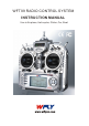
WFT09 RADIO CONTROL SYSTEM INSTRUCTION MANUAL Use in Airplane, Helicopter, Glider, Car, Boat
WFT09 INSTRUCTION CATALOGUE FLYING SAFETY WARNINGS-------------------------------------------- 1 Transmitter------------------------------------------------------------------- 2 Receiver---------------------------------------------------------------------- 4 Accessories------------------------------------------------------------------ 5 FEATURES------------------------------------------------------------------ 6 BUTTONS-------------------------------------------------------------------- 7 Opening Screen
WFT09 INSTRUCTION 18.
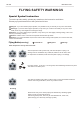
WFT09 INSTRUCTION FLYING SAFETY WARNINGS Special Symbol Instruction To use the product safely, please pay attention to the instruction as follows. Please pay special attention to the symbol as follows: Dangers:If you use it without proper operation, it is possible to hurt you seriously or may even cause death. Warnings:If you use it without proper operation, it may make you or others to hurt badly or may even cause death, and it may cause slight hurt or damage to things.
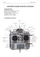
WFT09 INSTRUCTION CONTENTS AND SPECIFICATIONS TRANSMITTER MODEL NO.: WFT09H MODULATION: FM(PPM) and PCM OUTPUT POWER: ≤700mW POWER SUPPLY: 1.2V x 8 (9.
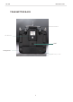
WFT09 INSTRUCTION TRANSMITTER BACK Handl e RF mo d u l e DSC Charge hole Battery co v e r 3
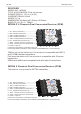
WFT09 INSTRUCTION RECEIVER MODEL NO.: WFR09 TYPE: 9 CH PCM/PPM, Dual conversion POWER SUPPLY: 1.2V x 4 (4.8V) CURRENT DRAIN: 9.5mA WEIGHT: 19 g DIMENSION: 44.88mm x27.90mm x16.
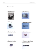
WFT09 INSTRUCTION Accessories 1 . RF 5. Neckstrap MODULE 2. Charger 6. Simulator cable 3 . Batter y holder 7. Switch har ness 4 . Batter y holder 8.
WFT09 INSTRUCTION FEATURES Computeriged transmitter. 192 x 64 dot matrix LCD, easy operating buttons. Metal slab shell. Adjustable antenna basement. Tightness and length of the control stick can be adjusted freely. Excellent touch of the stick movement. Full digital trim. Independent RF module for easy band exchange. Trainer function. 3 independence timer, all can be set to count down or increment. PCM and PPM modulation supported. Multi mixing function.
WFT09 INSTRUCTION Buttons MENU Menu button brings you to the function list of the transmitter. EXIT Exit button is to back the previous menu or exit edit. + This button is to increase the value. If you press it for a while, the increasing speed will be faster. This button is to decrease the value. If you press it for a while, the decreasing speed will be faster. Cursor buttons Move the cursor. OK The button in the middle of the direction buttons is the OK button.
WFT09 INSTRUCTION Opening ScreenI T urn on the power switch, the LCD displays as follows. Opening time Voltage Timer A Idle Model type Timer B Timer C Elevator trim display Throttle trim display Rudder trim display Aileron trim display Model name The opening screen displays the voltage, timer, model, aileron, throttle, elevator and rudder state. Menu Screen Turn on the transmitter, press the menu button, the LCD displays as follows. 1. Monitor 2. Dual rate & Exponential setting 3.
WFT09 INSTRUCTION System setting menu II Press Menu and t urn on the power switch, the LCD displays as follows. 1. Model selecting 2. Model name 3. Model setting 4. ATL 5. Modulation setting 6. Swash select 7. Stick setting 8. Rest setting 9. Send data 10. Receive data 11. Contrast setting 12. Engineer model 13. About 14. Language Skill If the transmitter alarms because of the user setting, press “-” button to exit.
WFT09 INSTRUCTION Trainer function Two WFT09 transmitters can transfer data and realize trainer function. Setting Method: 1).Data transfer function: use Trainer cable/Data transfer cable to connect two WFT09 transmitter. Select “Send data/receive data” in SYS setting to transfer the data. 2).Trainer function: use Trainer cable/Data transfer cable to connect two WFT09 transmitters. Insert RF module to the trainer transmitter, student transmitter doesn’t insert the RF module.
WFT09 INSTRUCTION SYSTEM SETTING 1. Monitor Monitor shows the servos’ movement situation. In PCM, this function is to describe the 9 channels output. In PPM, this function is to describe the first 7 channels output. Setting Method Press menu button, enter system setting, the first function is the monitor. 2. Dual rate & Exponential setting Dual rate is to adjust aileron, elevator and rudder travel range. The range is between 0%-120%.
WFT09 INSTRUCTION 3. Set dual rate Press direction button to select “D/R”, edit it. Edit one or two parameter. +/- buttons can increase or decrease the value. Press the OK button is to back default. 4. Set exponential Press direction button to select “EX”. Exponential can adjust aileron, throttle and rudder sensitivity as the stick at the middle. 5. Set curve point (normal/advanced) The box under “EX” shows the curve points. Select “Curve setting” in More setting function list.
WFT09 INSTRUCTION 4. End point It is to adjust the end of individual servo’s travel. The range is from 0% to 120%. Channel Side Value Setting Method Use up or down button to select End point, OK button is to enter editing. Steps: 1. Use direction buttons to select editing part. 2. Use +/- button or OK button to set the travel value. Press OK for a while backs to default. 3. Press EXIT after setting. 5. Sub trim Sub trim makes small changes or corrections to the neutral position of each servo.
WFT09 INSTRUCTION 6. Swash param setting This function is to adjust the aileron, elevator and pitch travel range of swash mixing mode. Setting Method Use up or down button to select Swash param setting, OK button is to enter editing. Steps: 1. Use direction buttons to select editing part. 2. Use +/- button to set the travel. Press OK button for a while is to back default(60%). 3. Press EXIT after setting. Effection direction Value 7.
WFT09 INSTRUCTION 8. Throttle curve setting 9. Pitch curve setting Throttle curve, together with the throttle stick, can be adjusted properly to maximize engine performance at a particular pitch setting. There are 2 to 11 points could be set, the range is between 0% to 120%. The transmitter can set the following curves: NORM, IDLE1, IDLE2, IDLE3. Normal curve is based on hovering, to maximize engine performance at a particular pitch setting.
WFT09 INSTRUCTION 11. Trim step setting This function is to changes the rate at which the trim moves when the TRIM LEVER is activated. The range is from 0 to 250. Generally larger trim steps are for models with large control throws or for first flights to ensure sufficient trim to properly correct the model. Smaller trim steps are later used to allow very fine adjustments in flight. Setting Method Use up or down button to select Trim step setting , OK button is to enter editing. Steps: 1.
WFT09 INSTRUCTION 13. Fly model switch This function is to select the flight mode. Fly mode Switch Fly mode statue 14. Throttle holding setting This function holds the engine in th idling position and disengages it from the THROTTLE STICK when SWITCH E(9 CH) or G (9CA) is moved. It is eommonly used to practice auto-rotation. Setting Method Use up or down button to select Throttle holding editing. Steps: 1. Use direction buttons to select editing part. 2. Use +/- button for proper adjustment, 3.