
User's Manual

Installation:
Directly download the code after connecting to the computer through a USB cable.
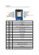
Pin No.
Pin Name
Pin Description
1
RST
Reset
2
A0
Analog Input
3
D0
GPIO16, used to wake up from deep sleep
4
D5
GPIO14,SPI (SCLK)
5
D6
GPIO12, SPI (MISO)
6
D7
GPIO13, SPI (MOSI)
7
D8
GPIO15,SPI (CS)
8
3V3
Power Supply
9
5V
Power Supply
10
G
Ground
11
D4
GPIO2, connected to on-board LED, boot fails if pulled LOW
12
D3
GPIO0, connected to FLASH button, boot fails if pulled LOW
13
D2
GPIO4, often used as SDA (I2C)
14
D1
GPIO5, often used as SCL (I2C)
15
RX
GPIO3,TXD0,CS1
16
TX
GPIO1, debug output at boot, boot fails if pulled LOW