ShelterCoat TM Custom Garage Program 28'W x 20'H Peak +/- 18" 45 cm / 1 2" Please read instructions COMPLETELY before assembly. This shelter MUST be securely anchored. THIS IS A TEMPORARY STRUCTURE AND NOT RECOMMENDED AS A PERMANENT STRUCTURE. Before you start: 5 or more individuals recommended for assembly. Assembly time is dependent upon the length of your building. Allow approximately 15 minutes for every foot in building length.
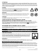
ATTENTION: This shelter product is manufactured with quality materials. It is designed to fit the ShelterLogic® Corp. custom fabric cover included. ShelterLogic® Corp. Shelters offer storage and protection from damage caused by sun, light rain, tree sap, animal / bird excrement and light snow. Please anchor this ShelterLogic® Corp. structure properly. See manual for more anchoring details. Proper anchoring, keeping cover tight and free of snow and debris is the responsibility of the consumer.
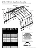
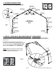
28'W x 20'H Peak Style Frame Assembly Please read and understand instructions completely before assembly. Lay out frame parts as shown. 1 End Rib 29,16 9 3,28,16 9 9 Middle Ribs Top Rail 5 1 End Rib 8 4 18,13,16 1 18,13,16 5 3 2 1 22 6 13 16 23 32 26 1 17,13,16 4 25 9 22 12 15 16 10 14 16 8 32 9 8 25 9 32 8 Cover Rail 23 26 24 23 31 25 21 12 15 16 30 9 12 28 10 16 14 19 16 8 31 9 10 14 16 9 11 21 11 31 14 Mfg.
NOTE: FRAME EXTENSION KIT Your model may have more middle ribs than shown in the illustration on pg.3. You will receive one extra rib for every extra 4 ft. of building length that you purchase. The basic frame assembly will remain the same. The cover will be the correct size for the length of the building. 28 ft. WIDTH 1. PLOTTING THE FRAME Before building your shelter, you should choose a flat area on your property and plot your shelter. A. Stake out the area for the shelter in the desired spot.
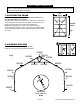
3. ASSEMBLE MIDDLE RIBS Assemble middle ribs as shown in Fig. 3. Securely fasten all of the joints with the hardware indicated. 800391 800384 800384 800436 00690 800383 11131 800385 800390 800389 800385 800088 800386 800386 Use #11131 5/16" x 2 3/4" L Bolts 800438 800438 Fig.3 800436 800436 800088 800088 4. INSTALL SIDE RAILS AND SHELTERLOCK® STABILIZERS A. Place assembled first end rib in the staked area. Place the ShelterLocks® (800372) on the uprights as shown in Figure 4.
5. CONNECT THE FIRST MIDDLE RIB AND INSTALL WIND BRACES Assemble upper Wind Brace with parts 802011 + 11005. Attach this and Wind Brace 800439 between the end rib and the first middle rib as shown in Figure 5. Bolts should be inserted facing inside of the shelter. A 00690 802011 11005 11130 11 0 05 80 20 11 Fig.
6. CONNECT THE REMAINING RIBS A. Use Side Rails 11102 to connect remaining ribs and rear end rib. B. Use Wind Braces 800439 and 802011 + 11005 between the end rib and the last middle rib as shown in Fig. 6. Fig.
7. INSTALL TOP RAIL: As with the Side Cross Rails, Use #11104 and #11102 Rails to make the Top Cross Rail: A. Place the first rail (#11104) under the end rib and secure it with bolt #11134 as shown in Fig.7A. HANDTIGHTEN this bolt. B. Connect the rails to each other, laying the #11102 cross rails over the middle ribs. Use bolt #11133. Fig.7B C. Place the last rail under the rear end rib. HAND-TIGHTEN this bolt. Fig.7A 11133 11134 800383 11102 02 111 11104 02 111 Fig.7B 00690 00690 Fig.8 8.
. INSTALL EASY-HOOK EARTH ANCHORS: A. The anchors should be positioned at the four corners and the remaining should be spaced evenly on both sides of the shelter. B. Using the provided steel driving rod and a sledge hammer, drive each anchor into the ground leaving approximately 8 inches of cable exposed above the surface. C. Wrap the cable around the driving rod and pull up on the cable to set the anchor. D. After the anchors are firmly set, wrap the cable around the foot, then close with a cable clamp.
. END AND DOOR PANEL INSTALLATION A. Hold end panel at the top center with white inner surface facing inside of the shelter. (If you purchased the white cover, the inner face has the visible weld seams at the webbing pocket.) Wrap the edges of the fabric panel around the end rib. B. Disconnect top cross rail (the horizontal pipes that run from front to back along the top) from the end rib. Pull the webbing (the black strap) below the cross rail. Reattach the top cross rail to the end rib. C.
. INSTALLING THE COVER ON THE FRAME A. Lay the cover on the ground next to the frame with the inside of the cover (the side with the pipe pockets) facing down and the webbing on the front and rear of the corner of the building. Position the cover so that it is centered to the frame, front to back. Fig. 11A END PANELS NOT SHOWN FOR CLARITY. Fig.11A B. Fold over the side closest to the frame so the pipe pocket is now accessible.
11. INSTALLING THE COVER ON THE FRAME - continued E. After cover is centered on frame, insert a Cover Rail (#11105) into each pocket on the inside of the cover in the roof. F. Use 3-Way (#11106) and 4-Way (#11107) Clamps to connect them to the ribs. Hand-tighten bolts (#11130). See Figure 11F. NOTE: To avoid damage to fabric, face bolt heads towards cover. G. Using cover rails, pull top portion of cover tightly downward and outward from the center and tighten bolts.
11. INSTALLING THE COVER ON THE FRAME - continued H. At the corners, insert the “S”- Hook on ratchet into hole on the leg bend. Insert the webbing into the spindle of the ratchet and pull tight. Wind the ratchet so that the webbing overlaps itself. See Figure 11G. I. Repeat these steps on the opposite side, then repeat this on the back side of the shelter. J. Adjust the cover front to back so that it is centered.
ShelterCoat TM Programme de Garage Personnalisé 28'/8,5m l. x 20'/6,1m h. Pointu +/- 18 po 45 cm Veuillez lire TOUTES les instructions avant d'entreprendre l'assemblage. Cet abri DOIT être bien ancré. CECI EST UNE STRUCTURE TEMPORAIRE, IL N'EST PAS RECOMMANDÉ D'EN FAIRE UNE STRUCTURE PERMANENTE. Avant de commencer : Il faut 5 personnes ou plus pour le montage. Le temps de montage dépend de la longueur de votre bâtiment. Veuillez prévoir environ 15 minutes pour chaque pied de longueur du bâtiment.
ATTENTION : Cet abri est fabriqué avec des matériaux de qualité. Il est conçu en fonction de la toile adaptée ShelterLogic® Corp. fournie. Les abris ShelterLogic® Corp. offrent de l’espace de rangement et de la protection contre les dommages causés par le soleil, la pluie légère, la sève, les excréments d’animaux ou d’oiseaux et la neige légère. Veuillez ancrer adéquatement cette structure ShelterLogic® Corp. Consultez le guide pour connaître les détails sur l’ancrage.
Abri à toit pointu, 8,5 m (larg.) x 6,1 m (haut.) - Assemblage Veuillez lire et vous assurer de bien comprendre TOUTES les instructions avant d'entreprendre l'assemblage. Étalez les pièces de l'armature, comme le montre l'illustration.
REMARQUE : NÉCESSAIRE DE RALLONGE D'ARMATURE Votre abri peut comporter davantage de nervures centrales que l'illustration de la page 16. Vous recevez une nervure additionnelle pour chaque section supplémentaire de 1,2 m. L'assemblage de l'armature de base reste le même. La taille de la toile correspondra à la longueur de l'abri. 1. TRACEZ L'EMPLACEMENT. Avant d’assembler l’abri, vous devez choisir une surface plane et y tracer son emplacement. A. Piquetez l’emplacement de l’abri à l’endroit choisi.
3. ASSEMBLEZ LES NERVURES CENTRALES Assemblez les nervures centrales comme le montre la fig. 3. Serrez bien tous les joints avec les fixations illustrées. 800391 800384 800384 800436 00690 800383 11131 800385 800390 800389 800385 800088 800386 800386 Utilisez les boulons n° 11131 (5/16 x 2 3/4 po) 800438 800438 Fig.3 800436 800436 800088 800088 4. INSTALLEZ LES RAILS LATÉRAUX ET LES STABILISATEURS SHELTERLOCK® A. Placez la nervure avant à l'emplacement piqueté.
5. RELIEZ LA PREMIÈRE NERVURE CENTRALE ET INSTALLEZ LES CONTREVENTEMENTS Assemblez contreventement supérieure avec des pièces 802011 + 11005. Fixez un contreventement (800439) entre la nervure d'extrémité et la première nervure centrale comme le montre la figure 5. Les boulons fixés aux traverses doivent être orientés vers l'intérieur de l'abri. A 00690 802011 11005 11130 80 04 42 Fig.
6. RELIEZ LES NERVURES RESTANTES A. Utilisez les rails latéraux (11102) pour relier les nervures restantes et la nervure d'extrémité arrière. B. Placez des contreventements (800439 et 802011 + 11005) entre la nervure d'extrémité et la dernière nervure centrale comme le montre la Fig. 6. Fig.
7. INSTALLEZ LA TRAVERSE SUPÉRIEURE À l'instar des traverses latérales, utilisez les traverses 11104 et 11102 pour composer la traverse supérieure. A. Placez la première traverse (11104) sous la nervure d'extrémité et fixez-la avec le boulon 11134 comme le montre la Fig.7A. Serrez ce boulon À LA MAIN. B. Reliez les traverses entres elles en plaçant les traverses 11102 sur les nervures centrales. Utilisez le boulon 11133 (voir la Fig. 7B). C. Placez la dernière traverse sous la nervure d'extrémité arrière.
9. INSTALLEZ LES ANCRAGES EASY-HOOK A. Des ancrages doivent être placés aux quatre coins, puis le reste des ancrages doivent être espacés également des deux côtés de l'abri. B. En utilisant la tige d'acier fournie et une masse, enfoncez chaque ancrage dans le sol en laissant dépasser environ 8 po de câble au-dessus de la surface. C. Enroulez le câble sur la tige et tirez sur le câble pour placer l'ancrage. D.
10. INSTALLEZ LE PANNEAU D'EXTRÉMITÉ ET LE PANNEAU DE PORTE A. Placez le panneau d’extrémité au centre de la partie supérieure de l’abri en orientant la surface interne vers l’intérieur de l’abri (pour la toile blanche, la surface interne est pourvue de joints de soudure visibles au fourreau de la courroie). Faites passer le rebord du panneau en tissu autour de la nervure d’extrémité. B.
11. INSTALLEZ LA TOILE SUR L’ARMATURE A. Étalez la toile sur le sol à côté de l’armature en plaçant l’intérieur de la toile (côté avec les fourreaux pour tuyaux) vers le bas et les courroies avant et arrière vers les coins de l'abri. Centrez la toile entre l’avant et l’arrière de l’armature (fig. 11A). PANNEAUX D'EXTRÉMITÉ NON ILLUSTRÉS Fig.11A B. Repliez le côté le plus proche de l'armature, de sorte que le fourreau pour tuyau soit accessible.
11. INSTALLEZ LA TOILE SUR L'ARMATURE (suite) E. Une fois la toile centrée sur l'armature, insérez un rail de toile (11105) dans chaque fourreau à l'intérieur de la toile, au plafond. F. Utilisez les brides à 3 voies (11106) et à 4 voies (11107) pour les fixer aux nervures. Serrez les boulons (11130) à la main. Voir la Figure 11F. REMARQUE : Pour éviter d'endommager la toile, orientez la tête des boulons vers la toile. G.
11. INSTALLEZ LA TOILE SUR L’ARMATURE - suite H. Dans les coins, insérez le "S" - Crochet à cliquet dans le trou sur le coude jambe. Insérez la sangle dans l'axe de la clé à cliquet et tirez fermement. Enroulez le rochet de sorte que la sangle elle-même chevauche. Voir Figure 11G. I. Répétez ces étapes sur le côté opposé, puis répétez cette sur la face arrière de l'abri. J. Ajuster le toile avant à l'arrière, afin qu'il soit centré.