SHO1 SHO1-2 Hybridization Oven Installation, Operation, and Maintenance Guide Previously Designated As Models 1013 1013-2 Sheldon Manufacturing Inc. P.O. Box 627 Cornelius, Oregon 97113 EMAIL: tech@Shellab.com INTERNET: http://www.Shellab.
Safety Notices A CAUTION notice denotes a hazard. It calls attention to an operating procedure, practice, or the like that, if not correctly performed or adhered to, could result in damage to the product or loss of important data. Do not proceed beyond a CAUTION notice until the indicated conditions are fully understood and met. A WARNING notice denotes a hazard.
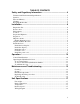
TABLE OF CONTENTS Safety and Regulatory Information ................................................ 4 Technical and Environmental Specifications.................................................................. 5 Symbols........................................................................................................................... 5 Fuses and Battery ............................................................................................................ 5 Cleaning ...........................
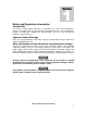
1 Section Safety and Regulatory Information Intended Use This unit is for professional, industrial, or educational use, where the preparation or testing of materials is done at approximately atmospheric pressure and no flammable, volatile, or combustible materials are being heated. This unit is not intended for hazardous or household use. Important Safety Warnings There are several important safety notices that you should always keep in mind when using the Hybridization Oven.
Technical and Environmental Specifications Below are the oven’s technical and environmental specifications.
2 Section Installation Prepare the Site Local city, county or other ordinances may govern the use of this equipment. If you have any questions about local requirements, please contact the appropriate local agency. The end user may perform installation, as it is unnecessary for this unit to be installed by a technician. Power source The electrical supply circuit to the oven must conform to all national and local electrical codes.
Inspect the Shipment Your satisfaction and safety require a complete understanding of this unit. Read the instructions thoroughly and be sure all operators are given adequate training before attempting to put the unit in service. Inspection The carrier, when accepting shipment, also accepts responsibility for safe delivery and is liable for loss or damage.
Return shipment process Save the shipping crate for future use. The shipping crate will be used to ship the oven back to the factory for repair, if needed. If for any reason you must return the unit, please contact Customer Service Representative for authorization. Please have the model number and serial number available when calling the Customer Service Representative. Fill out the Environment Health and Safety (EH&S) form completely and attach it to the oven before shipping.
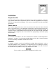
Install the rotator The rotator (also called rotisserie, Sheldon part number 9670511; see Figure 5) comes with your 1013 oven. To install the rotator into the oven: 1. Set the AC power switch to OFF. 2. Open the oven. Locate the rotator drive shaft coupling on the left side oven wall and the rotator shaft support bushing on the right side oven wall. See Figure 2. 3. Move the rotator into the oven and insert the two pins on the rotator drive shaft coupling into the two holes on the rotator coupling.
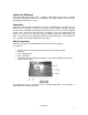
3 Section Operation Control Panel Interface The 1013 Hybridization Oven is operated using the control panel interface (see Figure 6), which is located on the front of the oven. Rotational speed control Use to set the rotator speed from 2 to 20 rpm. Turning the knob clockwise increases the rotator speed. Set to 0 (zero) to turn off the rotator. Heating indicator Lights continuously when the oven is heating. Blinks when the oven is at or near its set point.
Operating the Hybridization Oven To set a temperature Using the temperature controller: 1. Enter set point mode by pressing either or The digital display will start to blink. While blinking, the digital display shows the current set point. 2. Press or to enter the desired set point temperature. If the arrow pads are not pressed for five (5) seconds, the display will stop blinking and will read the temperature in the chamber.
To calibrate the oven Calibrate the oven: • After first installation in a working environment. • After each 3 months of use To calibrate the oven: 1. Install the rotator and load it with a typical number of chambers. 2. Turn on the oven and set to a typical operating temperature. 3. Allow the oven to stabilize for at least 1 hour. 4. Place a certified reference thermometer in the chamber near the sample area. 5.
4 Section Maintenance and Troubleshooting Cleaning To clean the unit: 1. Remove the rotator and drip tray. 2. Clean the oven using mild detergent. 3. Clean the rotator and drip tray using either the same solution used for the chamber, or an autoclave. Storage If the unit is to be turned off for any length of time, assure that the chamber and drip tray are dry and store at room temperature. Failure to do this may cause the interior to become contaminated.
Replacing the inline power fuse The unit is protected by an inline fuse located behind the power cord. If needed, replace the fuse as described below: 1. Turn off the oven and rotator, then disconnect from the power source. 2. Remove the power cord from the back of the oven. 3. Using a small, flat-bladed screwdriver pry the fuse holder from the back of the unit. See Figure 8. 4. Inspect the fuse in service. See Figure 9. Replace if blown with a 6.3 A, 250 V type T fuse.
Troubleshooting The following table shows a list of problems and their corresponding solutions. If these instructions do not correct the problem, call Customer Service for further assistance. Table 1 Problems and solutions Problem Action The unit will not turn on. 1 Verify that the power cord is plugged into the oven and power source. 2 Verify that the power switch is ON. 3 Check the fuse as described in “Replacing the inline power fuse” on page 15 and replace if blown.
Table 1 Problems and solutions (continued) Problem Action The indicated chamber temperature is unstable. Temperature range ±1 °C is normal. 1 Check to make sure the fan is working by checking the fan motor motion and feeling for air movement in the chamber. Verify movement of the cooling fan in the back of chamber. 2 Doors opening, air flow from heaters, and air flow from air conditioner units may radically change the ambient room temperature. Stabilize ambient conditions.
5 Section Unit Specifications Net weight Unloaded unit weight, without rotator: 75.0 lbs (34.0 kg) Interior dimensions 12.5 in wide x 12 in deep x 14.5 in high (31.8 cm x 30.5 cm x 36.8 cm) Temperature Operating temperature range: Amb. +5 °C to 70 °C Precision: 0.
Wiring Diagram Unit Specifications 18