HUMIDITY CHAMBER SHC10 SHC10R SHC28 SHC28R SHC10-2 SHC10R-2 SHC28-2 SHC28R-2 PREVIOUSLY DESIGNATED AS : HC9 HC9-2/ HC9R HC9R-2 HC30 HC30-2 / HC30R HC30R-2 W ITH MICRO PROCESSOR CONTROL INSTALLATION AND OPERATION INSTRUCTIONS Revised 01/2014 4861578 Sheldon Manufacturing Inc. P.O. Box 627 Cornelius, Oregon 97113 EMAIL: tech@Shellab.com INTERNET: http://www.Shellab.
TABLE OF CONTENTS SECTION 1.0 RECEIVING AND INSPECTION SECTION 2.0 GRAPHIC SYMBOLS SECTION 3.0 INSTALLATION AND FACILITIES REQUIREMENTS SECTION 4.0 CONTROL OVERVIEW SECTION 5.0 THEORY OF OPERATION SECTION 6.0 OPERATION SECTION 7.0 CHART RECORDER INSTALLATION SECTION 8.0 MAINTENANCE SECTION 9.0 TROUBLESHOOTING SECTION 10.
1 Section RECEIVING AND INSPECTION Your satisfaction and safety require a complete understanding of this unit, including its proper function and operational characteristics. Read the instructions thoroughly and be sure that all operators are given adequate training before attempting to put the unit into service. NOTE: This equipment must be used only for its intended application; any alterations or modifications will void your warranty. 1.
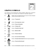
2 Section GRAPHIC SYMBOLS Your incubator has been provided with a display of graphic symbols which is designed to help in identifying the use and function of the available user adjustable components. 2.1 Indicates that you should consult your manual for further description or discussion of a control or user item. 2.2 Indicates "Temperature". 2.3 Indicates "Over-temperature safety". 2.4 C Indicates "Degrees Centigrade". 2.5 Indicates "AC power ON". 2.6 Indicates "Humidifier Water Low". 2.
3 Section INSTALLATION Local city, county or other ordinances may govern the use of this equipment. If you have any questions about local requirements, please contact the appropriate local agency. Installation may be performed by the end user. It is unnecessary for this unit to be installed by a technician.
and assure all volatile or flammable cleaners are evaporated and dry before reattaching the unit to the power supply. 3.6 Humidification Water Supply: On the back of the body there is a 1/4" compression fitting marked WATER IN. This fitting should only be plumbed to a DISTILLED WATER supply source.
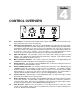
4 Section CONTROL OVERVIEW 4.1 4.2 4.3 4.4 4.5 4.6 4.7 4.8 4.9 Power Switch: The main power I/O (On/Off) switch controls all power to the unit, and must be in the I/On position before any systems are operational. High Limit Safety Thermostat: This control is marked SAFETY and is adjacent to the power switch. It is completely independent of the Main Temperature Controller and guards against any failure which would allow the temperature to rise past set point.
5 Section THEORY OF OPERATION These humidity chambers are designed to maintain temperature and relative humidity at set points controllable by the operator at the front panel. Air is constantly being circulated through the chamber, monitored for comparison to set points and treated if necessary. On all units, heating is done by electric resistance heaters that turn off and on for temperature control.
6 Section OPERATION It is recommended that your unit be allowed to reach operating temperature before engaging the humidifying system. This requires setting the RH set point to 0 (zero) until the unit is at operating temperature. See Section 6.6 for changing the RH set point. 6.1 Turn the power switch to the I/ON position. Turn the High Limit Safety thermostat to its maximum position, clockwise and place the shelves in the chamber. 6.
7 Section CHART RECORDER INSTALLATION Please note that the following information is a general guide for installation. Before attempting installation please read the instructions provided with your chart recorder thoroughly for specific installation instructions. NOTE: Unplug unit from the power supply before installing the Chart Recorder. 7.1 Remove cover for Chart Recorder, located on the right side of control panel. 7.2 Remove steel plate from the back of the Chart Recorder. 7.
8 Section MAINTENANCE NOTE: Prior to any maintenance or service on this unit, disconnect power cord from the power supply. Service of any electrical components should only be performed by personnel who are qualified and familiar with the use and function of these components. 8.1 Clean the chamber interior. Remove and clean shelves and shelf clips on a periodic basis using a disinfectant that is suitable to your application.
9 Section TROUBLESHOOTING Always make a visual inspection of the unit and control console when troubleshooting. Look for loose or disconnected wires which may be the source of the trouble. The incubator is designed so that no internal electrical servicing should be required under normal conditions. If electrical servicing is necessary, it should be performed by qualified service personnel. For information on where to reach technical service please see the manual cover.
1/ verify that controller is asking for heat by looking for Heating light – if pilot light is not on continuously, there is a problem with the controller 2/ check amperage – amperage should be virtually at maximum rated (data plate) amperage 3/ do all controller functions work? 4/ is the Safety Thermostat set high enough? – for diagnostics, should be turned fully CCW with the pilot light never on 5/ has the fuse/circuit breaker blown? Indicated chamber temperature unstable 1/ ±0.
1/ assure that exhaust fan is working 2/ assure that exhaust fan blower casing is free of pooled water 3/ check solid state relay 4/ set point has to be 10 percentage points below reading on control to turn exhaust fan on 5/ injection valve stuck open 6/ condensate drain tube plugged and pool of water in bottom of chamber Can't adjust set points or calibration 1/ confirm all wire connections 2/ confirm software revision 3/ call Customer Service Steam generator not working 1/ check if fill solenoid, injectio
Door not sealing 1/ adjust hinge blocks or twist the door. 2/ Confirm that unit has not been damaged and body is not square. Motor doesn't move 1/ if shaft spins freely: check connections to motor and check voltage to motor; 2/ if shaft rubs or is frozen, relieve binding and retest Motor makes noise 1) Make sure that the fan or blower wheel is not contacting its housing. Adjust the motor mounting bracket position to re-center the fan or blower wheel, if necessary.
10 Section PARTS LISTS SHC10 and SHC10-2 (HC9 and HC9-2) SHC10R and SHC10R-2 (HC9R and HC9R-2) SHC10 (HC9) SHC10-2 (HC9-2) SHC10R (HC9R) SCH10R-2 115V 220V 115V (HC9R-2) 220V Adjustable Feet 2700500 2700500 2700500 2700500 Blower Wheel, Aluminum 2600535 2600535 2600535 2600535 Blower Wheel, Plastic 2600544 2600544 2600544 2600544 Circuit Breaker 1100500 1100500 1100500 1100500 DESCRIPTION Element 2350563 2350554 2350562 2350554 Fan Blade 2600551 2600551 2600551 2600551
SHC28 (HC30) and SHC28-2 (HC30R) SHC28R (HC30R) and SHC28R-2 (HC30R-2) SHC28 (HC30) SHC28-2 (HC30-2) SHC28R (HC30R) 115V 220V 115V SHC28R-2 (HC30R-2) 220V Blower Wheel, Aluminum 2600535 2600535 2600535 2600535 Blower Wheel, Plastic 2600544 2600544 2600544 2600544 Element, Main 2350563 2350554 2350563 2350554 Fan Blower Wheel 2600504 2600504 2600504 2600504 Fan Motor 4880564 4880563 4880564 4880563 Float Switch 7850563 7850563 7850563 7850563 Humidity Control 1750553 17
UNIT SPECIFICATIONS Weight SHC10 SHC10-2 (HC9 HC9-2) SHC10R SHC10R-2 (HC9R HC9R-2) SHC28 SHC28-2 (HC30 HC30-2) SHC28R SHC28R-2 (HC30R HCR30-2) Dimensions SHC10 SHC10-2 (HC9 HC9-2) SHC10R SHC10R-2 (HC9R HC9R-2) SHC28 SHC28-2 (HC30 HC30-2) SHC28R SHC28R-2 (HC30R HCR30-2) Capacity SHC10 SHC10-2 (HC9 HC9-2) SHC10R SHC10R-2 (HC9R HC9R-2) SHC28 SHC28-2 (HC30 HC30-2) SHC28R SHC28R-2 (HC30R HCR30-2) Temperature SHC10 SHC10-2 (HC9 HC9-2) SHC10R SHC10R-2 (HC9R HC9R-2) SHC28 SHC28-2 (HC30 HC30-2) SHC28R SHC28R-2 (H
RELATIVE HUMIDITY CHART
WIRING DIAGRAM SHC10 (HC9) (9851449) POWER CORD 1800517 CURCUIT BREAKER 1100500 BLACK WHITE BLACK GREEN LIGHTED SWITCH 7850570 BLOWER MOTOR 4880504 WHITE BM P2 WHITE BLACK ORANGE BLUE P1 BLACK RED P3 P13 P4 BLACK P10 WHITE 1 4 P8 BLACK WHITE WHITE FAN 2 3 RH CONTROL 1750553 P7 HUMIDIYT EXHAUST FAN 4880564 P9 SOLID STATE RELAY 7030533 P5 WHITE YELLOW HUMIDITY LIGHT 4650554 BLACK 22G P12 RH SENSOR 4100504 HUMIDITY INJECTION SOLENOID 8600576 BLACK P5 RED 22G WHITE 18G YEL
WIRING DIAGRAM SHC10-2 (HC9-2) (9851450) WHITE 2800503 EMI FILTER WHITE POWER FUSED INLET 4200505 BLACK WHITE BLACK WHITE BLACK GREEN LIGHTED SWITCH 7850570 BLOWER MOTOR 4880504 P2 P1 ORANGE P3 WHITE P4 BM BLACK P10 RED BLACK P7 BROWN FAN WHITE P9 SOLID STATE RELAY 7030533 P5 WHITE YELLOW HUMIDITY LIGHT 4650554 BLACK 18G 12VDC POWER SUPPLY 6750507 IN OUT P20 RED 22G P12 RH SENSOR 4100504 BLACK 22G HUMIDITY INJECTION SOLENOID 8600578 BLACK P5 WHITE 18G YELLOW P12 P22 W
WIRING DIAGRAM SHC10R (HC9R) (9851451) POWER CORD 1800517 CURCUIT BREAKER 1100500 BLACK WHITE BLACK GREEN LIGHTED SWITCH 7850570 BLOWER MOTOR 4880504 WHITE BM P2 RED WHITE BLACK ORANGE BLUE P1 BLACK P3 P13 P4 BLACK P10 WHITE 1 4 P8 BLACK WHITE WHITE FAN 2 3 RH CONTROL 1750553 P7 HUMIDIYT EXHAUST FAN 4880564 P9 SOLID STATE RELAY 7030533 P5 WHITE YELLOW HUMIDITY LIGHT 4650554 RED 22G RH SENSOR 4100504 BLACK 22G HUMIDITY INJECTION SOLENOID 8600576 BLACK P5 P12 IN OUT 12VD
WIRING DIAGRAM SHC10R-2 (HC9R-2) (9851452) WHITE 2800503 EMI FILTER WHITE POWER FUSED INLET 4200505 BLACK WHITE BLACK GREEN LIGHTED SWITCH 7850570 BLOWER MOTOR 4880504 WHITE WHITE BM BLACK BLACK ORANGE P2 RED P1 BLUE P3 P13 P4 BLACK WHITE 1 4 P8 BLACK 2 3 RH CONTROL 1750554 WHITE P7 HUMIDIYT EXHAUST FAN 4880563 BROWN WHITE FAN P9 SOLID STATE RELAY 7030533 YELLOW WHITE P5 HUMIDITY LIGHT 4650554 P12 RH SENSOR 4100504 HUMIDITY INJECTION SOLENOID 8600578 BLACK P5 RED 22G BL
WIRING DIAGRAM SHC28 (HC30) (9851453) CIRCUIT BREAKER 1100500 POWER CORD 1800529 WHITE BLACK WHITE BLACK GREEN LIGHTED SWITCH 7850570 BLOWER MOTOR 4880504 P2 P1 ORANGE P3 WHITE P4 BM P10 BLUE RED BLACK WHITE BLACK BROWN WHITE FAN P9 SOLID STATE RELAY 7030533 P5 WHITE YELLOW P20 12VDC POWER SUPPLY 6750507 BLACK 18G RED 22G IN OUT HUMIDITY LIGHT 4650554 P12 RH SENSOR 4100504 BLACK 22G HUMIDITY INJECTION SOLENOID 8600576 BLACK P5 WHITE 18G P12 P22 WHITE YELLOW P16 QUEN
WIRING DIAGRAM SHC28-2 (HC30-2) (9851454) WHITE 2800503 EMI FILTER WHITE POWER FUSED INLET 4200505 BLACK WHITE BLACK WHITE BLACK GREEN LIGHTED SWITCH 7850570 BLOWER MOTOR 4880504 P2 P1 ORANGE P3 WHITE P4 BM BLACK P10 RED BLACK P7 BROWN FAN WHITE P9 SOLID STATE RELAY 7030533 P5 WHITE YELLOW HUMIDITY LIGHT 4650554 BLACK 18G 12VDC POWER SUPPLY 6750507 IN OUT P20 RED 22G P12 RH SENSOR 4100504 BLACK 22G HUMIDITY INJECTION SOLENOID 8600578 BLACK P5 WHITE 18G YELLOW P12 P22 W
WIRING DIAGRAM SHC28R (HC30R) (9851455) POWER CORD 1800517 CURCUIT BREAKER 1100500 BLACK WHITE BLACK GREEN LIGHTED SWITCH 7850570 BLOWER MOTOR 4880504 WHITE BM P2 WHITE BLACK ORANGE BLUE P1 BLACK RED P3 P13 P4 BLACK P10 WHITE 1 4 P8 BLACK WHITE WHITE FAN 2 3 RH CONTROL 1750553 P7 HUMIDIYT EXHAUST FAN 4880564 P9 SOLID STATE RELAY 7030533 P5 WHITE YELLOW HUMIDITY LIGHT 4650554 P12 RH SENSOR 4100504 HUMIDITY INJECTION SOLENOID 8600576 BLACK P5 RED 22G BLACK 22G WHITE 18G YE
WIRING DIAGRAM SHC28R-2 (HC30R-2) (9851456) WHITE 2800503 EMI FILTER WHITE POWER FUSED INLET 4200505 BLACK WHITE BLACK GREEN LIGHTED SWITCH 7850570 BLOWER MOTOR 4880504 WHITE WHITE BM BLACK BLACK ORANGE P2 RED P1 BLUE P3 P13 P4 BLACK WHITE 1 4 P8 BLACK 2 3 RH CONTROL 1750554 WHITE P7 HUMIDIYT EXHAUST FAN 4880563 BROWN WHITE FAN P9 SOLID STATE RELAY 7030533 YELLOW WHITE P5 HUMIDITY LIGHT 4650554 P12 RH SENSOR 4100504 HUMIDITY INJECTION SOLENOID 8600578 BLACK P5 RED 22G BL