MICROPROCESSOR CONTROLLED OVEN SGO5 SGO5-2 PREVIOUSLY DESIGNATED CE5G CE5G-2 Revised 12/2013 4861568 INSTALLATION AND OPERATION MANUAL Sheldon Manufacturing Inc. P.O. Box 627 Cornelius, Oregon 97113 EMAIL: tech@Shellab.com INTERNET: http://www.Shellab.
TABLE OF CONTENTS SECTION 1.0 RECEIVING AND INSPECTION SECTION 2.0 GRAPHIC SYMBOLS SECTION 3.0 INSTALLATION SECTION 4.0 PRECAUTIONS SECTION 5.0 CONTROL PANEL OVERVIEW SECTION 6.0 OPERATION SECTION 7.0 MAINTENANCE SECTION 8.0 TROUBLESHOOTING SECTION 9.
1 Section RECEIVING AND INSPECTION Your satisfaction and safety require a complete understanding of this unit. Read the instructions thoroughly and be sure that all users are given adequate training before attempting to use this unit. Note: This equipment must be used only for its intended purpose; any alterations or modifications will void your warranty. 1.1 Inspection: The carrier, when accepting shipment, also accepts responsibility for safe delivery and is liable for loss or damage claims.
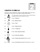
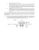
2 Section GRAPHIC SYMBOLS Your oven has been provided with a display of graphic symbols which should help in identifying the use and function of the available user adjustable components. 2.1 This symbol indicates that you should consult your manual for further description or discussion of a control or user item. 2.2 Indicates "AC Power". 2.3 Indicates "Manual Control". 2.4 Indicates "Timer". 2.5 C Indicates "Degrees Celsius". 2.6 Indicates "Temperature". 2.
3 Section INSTALLATION Local city, county or other ordinances may govern the use of this equipment. If you have any questions about local requirements, please contact the appropriate local agency. Installation may be performed by the end user. Under normal circumstance this unit is intended for use indoors, at room temperatures between 5 and 40 C, at no greater than 80% Relative Humidity ( at 25C ) and with a supply voltage that does not vary by more than 10%.
4 Section PRECAUTIONS 4.1 The bottom surface of the chamber should not be used as a work surface. 4.2 This unit has been designed with a dampered vent from the chamber. In order to work effectively and safely, some precautions will need to be taken by the operator. A. B. C. In most applications, the exhaust damper will need to be opened during drying or degassing for best results. THIS OVEN IS NOT DESIGNED TO HANDLE COMBUSTIBLE GASSES AND IS NOT AN EXPLOSION PROOF UNIT.
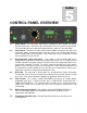
5 Section CONTROL PANEL OVERVIEW 5.1 Power Switch: The main power switch on the control panel (green lighted I/O) controls all power to the oven. It must be in the I/On position before any systems are operational. The green pilot light in the switch will be lighted when the switch is in the ON position. 5.2 Timer Switch: The black I/O power switch marked TIMER is located to the right of the main power switch. It controls the power to the time circuit.
6 Section OPERATION 6.1 Connection to Power Supply: Assure that the electrical power supply is properly configured and rated for the oven and plug the unit cord into the receptacle. 6.2 Push the main power switch to the On position. The digital temperature display will indicate a temperature value. Turn the Overtemperature Safety Thermostat to its maximum position, clockwise using a coin or flat head screwdriver. 6.
values between 0 and 5 to be set (digit 3). C. One Minute Function: After the correct ten minutes value is set, push the RESET pad again. The blinking decimal point will move one digit to the right beyond digit 4 and be located at the extreme bottom right of the display. With the display in this mode, pushing the UP or DOWN arrow pad will increase or decrease the one minute function allowing the value of digit 4 to be adjusted between 0 and 9. D. Activation: Pause until the timer stops blinking.
7 Section MAINTENANCE Note: Disconnect the power cord from the power source before performing any service or maintenance on this unit. 7.1 Cleaning: Cleaning and decontamination are recommended on a regular basis. To prepare the unit for cleaning, remove all interior parts if assembled, such as shelves and shelf clips. First clean the chamber with soap and water, rinse and let dry. To decontaminate use a solution that is appropriate for your application.
8 Section TROUBLESHOOTING TEMPERATURE Temperature too high. 1/ Controller set too high-see section 6.3 2/ Controller failed on – call Customer Service. 3/ Wiring error – call Customer Service. Display reads "HI" or "400"+. Probe is unplugged, is broken or wire to sensor is broken – trace wire from display to probe; move wire and watch display to see intermittent problems Chamber temp spikes over set point and then settles to set point. Recalibrate – see section 6.4.
1/ Check amperage – amperage should be virtually at maximum rated (data plate) amperage. 2/ do all controller functions work? 3/ Is the Safety Thermostat set high enough? – for diagnostics, should be fully clockwise with the OTP light never on. 4/ Has the fuse/circuit breaker blown? 5/ Has timer turned unit off? Indicated chamber temperature unstable 1/ ±0.1 may be normal. 2/ For G suffix models: may vary ±2.0 degrees. 3/ For F suffix models: is fan working? –verify movement of air in chamber.
1) Make sure that the fan or blower wheel is not contacting its housing. Adjust the motor mounting bracket position to re-center the fan or blower wheel, if necessary. 2) Check the fan or blower wheel for damage or out of balance condition. Replace the fan or blower wheel if it is damaged or out of balance. 3) Turn the motor shaft to make sure that it spins freely. If it binds or the bearings make a rubbing or scrapping sound then replace the motor. Door not sealing 1/ Adjust hinge blocks or twist the door.
9 Section PARTS LIST Description EMI Filter Adjustable Feet Control Knob Cord Set Door Latch Fuse Holder Fuse, 10 Amp 250V Fuse, 16 Amp I/O (On/Off) Power Switch Overtemperature Safety Thermostat Pilot Lamp, Green Pilot Lamp, OTP Red Shelf Clips Shelf Solid State Relay Timer Switch Main Control W/Timer Heating Element 115v 220V 2800503 2700512 4450506 1800510 3800605 N/A N/A 3300513 7850570 1750615 4650554 4650553 1250511 5130725 7030527 7850579 1750675 9570821 2800502 2700512 4450506 1800500 3800605 3
UNIT SPECIFICATIONS Weight Shipping Net All Models 200 lbs. 93 lbs. Dimensions Exterior WxDxH (in.) Interior WxDxH (in.) All Models 30.00 x 25.563 x 38.0 Capacity Cubic Feet All Models 5.0 Temperature All Models 21.00 x 19.50 x 21.00 Range Uniformity Recovery 10 above amb. to 225C +3.0C at 110C 9 min.
WIRING DIAGRAM All Models 16