AIR JACKETED CO2 INCUBATORS SCO5A SCO5A-2 SCO10A SCO10A-2 Previously designated as 5215 5215-2 5230 5230-2 INSTALLATION AND OPERATION MANUAL Revised 11/2013 4861507 Sheldon Manufacturing Inc. P.O. Box 627 Cornelius, Oregon 97113 EMAIL: tech@Shellab.com INTERNET: http://www.Shellab.
TABLE OF CONTENTS SECTION 1.0 RECEIVING AND INSPECTION SECTION 2.0 INSTALLATION SECTION 3.0 GRAPHIC SYMBOL SECTION 4.0 CONTROLS OVERVIEW SECTION 5.0 OPERATION SECTION 6.0 CALABRATION AND READING A FYRITE SECTION 7.0 MAINTENANCE SECTION 8.0 HEPA C02 FILTER SECTION 8.0 TROUBLESHOOTING SECTION 9.
Section RECEIVING AND INSPECTION 1 Your satisfaction and safety require a complete understanding of this unit. Read the instructions thoroughly and be sure all operators are given adequate training before attempting to put the unit in use. NOTE: This equipment must be used only for its intended application; any alterations or modifications will void your warranty. 1.1 Inspection: The carrier, when accepting shipment, also accepts responsibility for safe delivery and is liable for loss or damage.
Section INSTALLATION 2 Local city, county, or other ordinances may govern the use of this equipment. If you have any questions about local requirements, please contact the appropriate local agency. Installation may be performed by the end user. Under normal circumstances this unit is intended for use indoors, at room temperatures between 5 and 35C, at no greater than 80% Relative Humidity (at 25) and with a supply voltage that does not vary by more than 10%.
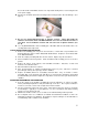
Assure all volatile or flammable cleaners are evaporated and dry before reconnecting the unit to the power supply. B. Special care should be taken when cleaning around sensing heads to Prevent damage. (See figure 1) Figure 1 C. Do not use chlorine-based bleaches or abrasive cleaners. These will modify the stainless steel interior finish. DO NOT USE hard tools such as metal wire brushes or steel wool. Use non-abrasive cleaners and soft tools such as plastic brushes. (See 7.1–A) D.
2.6 Place shelves in chamber as desired.
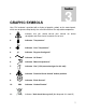
Section GRAPHIC SYMBOLS 3 Your CO2 incubator is provided with a display of graphic symbols on the control panel, which are designed to help identify the use and function of the adjustable components. 1. Indicates that you should consult your manual for further description and discussion of a control or user item. 2. Indicates “Temperature” 3. Indicates “Over Temperature” 4. C Indicates “Degrees Centigrade” 5. Indicates “AC Power” 6. Indicates “Manual Adjustment” 7.
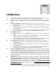
Section CONTROL PANEL OVERVIEW (See Figure 1) 4 Figure 1 All controls are located on the front panel. Units with a detachable cord have a fused inlet located at the top rear of the incubator. This inlet has a recessed male plug, fuse and an EMI filtering system designed to filter out electrical interference. This inlet also prevents any internally generated interference from feeding out to the power grid. 4.
Section OPERATION 5.1 5.2 5.3 5.4 5.5 5.6 5.7 5 Check power supply against unit serial plate; they must match. Be certain that the fuse is installed in the power inlet of the unit. Plug service cord into the electrical outlet. Push power switch to the ON position, and turn the High Limit Thermostat to its maximum position, clockwise. Temperatures must be set before CO2 connection and adjustments are made. Setting the Temperature: Inputting the set point on the controls is a very easy process. A.
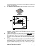
5.8 should be changed and the pan cleaned at least once a week to help control contamination and to maintain proper surface tension. CO2 Supply System and Control System: The CO2 system is rated for input pressures between 5 to 40 PSI which should never be exceeded at any time Humidity Pan PLUMBING DIAGRAM (figure 2) A. B. C. D. The CO2 inlet fitting is located at the back of the unit near the top (see Figure 2). It is marked CO2 TO CHAMBER.
E. F. G. The micro processor CO2 control system interprets the information from the CO2 sensor, displays the CO2 concentration directly on the digital display, reads the CO2 set point and controls the percentage of CO2 in the incubator chamber. The CO2 sensors operate under the principal that a certain frequency of infrared light is absorbed by CO2. The more CO2 is present the more light is absorbed.
Section FYRITE CO2 CHECKING 6 A Bacharach FYRITE CO Gas Analyzer is recommended to measure CO concentrations in the incubator chamber. This test instrument is not supplied with the incubator but is readily available from your dealer. Follow the instructions provided with each Fyrite instrument carefully to insure correct and accurate readings. Your incubator has a chamber sampling port, marked as such, at the top right side of the body. 1.
Section MAINTENANCE 7 NOTE: Prior to any maintenance or service on the unit, disconnect service cord from the power supply. 7.1 Cleaning: Disinfect the incubator interior on a regular basis. To prepare the incubator for cleaning remove the shelves and shelf slides. These stainless steel parts are autoclavable. A. First clean removed parts and interior with soap and water. To decontaminate use a disinfectant that is suitable for your application.
Section HEPA CO2 FILTER 8 The CO2 Incubator design features a HEPA filtration system with a patented copper housing. (Patent Number 6,333,004) As the chamber air is drawn through the filter system, airborne microbes and isolated particulates are not only removed from the air, but destroyed as well. It is through copper oxidation that the contaminants are actually killed. The HEPA filter is easily replaced without the need of any tools and has an efficiency rating of 99.97% at 0.3 microns.
Section TROUBLESHOOTING 9 Always make a visual inspection of the incubator and control console when troubleshooting. Look for loose or disconnected wires or tubing which may be the source of the problem. The incubator is designed so that no internal electrical servicing should be required under normal conditions. If electrical servicing is necessary, qualified service personnel should perform it only. For information on where to reach technical service please see the manual cover.
Overshoots set point and continues to rise - display and Fyrite match Debris in solenoid causing it to leak continuously Rises very slowly 1/ Filter overly dirty or partially plugged 2/ Hose kinked or leaking 3/ CO2 tank regulator set too low. 4/ CO2 tank near empty Never rises 1/ CO2 filter plugged 2/ CO2hose blockage 3/ CO2tank empty 4/ Set point is at 0.0 and has not been reset. 5/ CO2tank regulator not on Display and Fyrite reading do not match 1/ Old Fyrite fluid. 2/ Out of calibration.
1/ Make sure that the fan or blower wheel is not contacting its housing. Adjust the motor mounting bracket position to re-center the fan or blower wheel, if necessary. 2/ Check the fan or blower wheel for damage or out of balance condition. Replace the fan or blower wheel if it is damaged or out of balance. 3/ Turn the motor shaft to make sure that it spins freely. If it binds or the bearings make a rubbing or scrapping sound then replace the motor.
Section 10 PARTS LIST Description 115V 220V 4 TO 20mA BOARD 1750667 1750667 Chamber Gasket, 8 feet 3450546 3450546 Circulating Fan 4880564 4880563 CO2 Display Board 1750660 1750660 CO2 Fan Motor 4880508 4880507 CO2 Filter 2800525 2800525 Door Heater 2350550 2350550 Door Switch 7850578 7850578 Element 9570902 9570903 Fuse, 6.
UNIT SPECIFICATIONS Weight Shipping Net SCO5A (5212) 195 134 SCO5A-2 (5212-2) 195 134 SCO10A (5230) 390 268 SCO10A-2 (5230-2) 390 268 Dimensions Exterior WxDxH (in.) Interior WxDxH (in.) SCO5A (5212) 26.75 X 27 X 38 20.5 X 20 X 23.25 SCO5A-2 (5212-2) 26.75 X 27 X 38 20.5 X 20 X 23.25 SCO10A (5230) 26.75 X 27 X 76 20.5 X 20 X 23.25 SCO10A-2 (5230-2) 26.75 X 27 X 76 20.5 X 20 X 23.
TO 20mA Board Conversions CO2 @ 4mA=0% CO2 Temperature @ 4mA=0° Celsius CO2 @ 20mA=20% CO2 Temperature @ 20mA=70° Celsius INCUBATOR ACCESSORIES 1. 2. 3. 4. 5. CO2 Tank Switch Fyrite CO2 Gas Analyzer In-Line Filter HEPA Filter Caster Platform Model Amp Voltage Hertz SCO5A (5212) 6.0 amp 110-120V~ 50/60 Hz SCO5A-2 (5212-2) 3.0 amp 208-240V~ 50/60 Hz SCO10A (5230) 6.0 amp 110-120V~ 50/60 Hz SCO10A-2 (5230-2) 3.
WIRE DIAGRAM IEC FUSED FILTERED INLET 104179 115V - 10A - 3300516 230V - 6.3A - 3300515 BLK WHT WHT 115V - NOT USED 230V - 6.3A - 3300515 MAIN POWERSWITCH 7850532 BLK AIR JACKET FAN BLK BLK WHT WHT BLK 115V - 100909 230V - 103328 CO2 HEATER - 6W 115V - 210002 230V - 210001 BLK WHT 200021 BLK 18G WHT 18G MAIN PROBE 6750507 DOOR PROBE 1750667 12VDC POWER SUPPLY RING PROBE BUSS BUSS MAINPROBE 1750714 TEMPDISP 37.0 1750660 CO2DISP 5.