
Installation Guide
For the third week, you can regulate the heat as you would normally. The maximum output from the heating cables must not
exceed 60W/m
2
. When using area rugs or runners, the normal surface temperature of the wood may rise higher than
recommended. The oor’s surface temperature must not exceed 28˚C (82˚F). Please note: we do not warrant against slight
gaps that might develop between the oor panels when heating is active or due to changes in atmospheric conditions.
CAUTION: WOOD DUST
The International Agency for Research on Cancer has classied wood dust as a nasal carcinogen. The sawing,
sanding, and/or machining of wood products can produce wood dust that can cause respiratory, eye, and skin
irritations. Equipment should be equipped with a dust collector to reduce airborne wood dust. Wear an appropriate
NIOSH designated dust mask to reduce exposure to airborne wood dust. Avoid contact with eyes and skin. In case of
irritation, ush eyes or skin with water for at least 15 minutes. In cases of severe irritation; seek immediate medical
attention. For further technical or installation questions or to request a Product Specication Data Sheet contact the
manufacturer .
Attention California Installers & Consumers
WARNING
Installation of this product and wood product may create wood dust, which is known to the State of California to
cause cancer.
BASIC INSTALLATION
For installation on concrete oors or any oors over a crawl space a vapor retarder or 2in1 underlayment MUST be laid down rst. For Concrete use 6mil
poly, run the poly 2" (5 cm) up walls and overlap seams 18" (45 cm). Tape seams when installing over concrete. Do not tape seams over any wood
suboor.
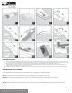
All ooring installations require foam underlay. Run the foam underlay in the same direction as the panels. Underlay should be butted side by side with
no overlap. Tape seams together, Or use a 2 n1 type underlayment as shown inDiagram 2.
You will need to remove the tongue, on the long side of the panels that face the wall, from the appropriate amount of panels for your rst row. This is to
ensure that the decorative surface is well under the nished trim when installed. Use a utility knife to score through the tongue several times until it
easily snaps off. Diagram 3.
Start in a corner by placing the rst panel with its trimmed side facing the wall. Use spacers along each wall to maintain an expansion space of 1/2" (12
mm) between the wall and the ooring. Diagram 4.
REMEMBER THAT THIS PRODUCT IS PRIMARILY WOOD AND NEEDS ROOM TO EXPAND AND CONTRACT. AT NO POINT SHOULD YOU ATTACH THE
FLOOR TO ANY SURFACE. ALSO, FLOOR SHOULD NOT RUN FOR MORE THAN 26' (8 METERS) IN WIDTH BY 40' (12 METERS) IN LENGTH. FLOOR
EXCEEDING THESE DIMENSIONS NEEDS TO BE SEPARATED IN AREAS SMALLER THAN 8 X 12 METERS USING T MOLDING. ROOMS SEPARATED BY AN
OPENING OF 36" (915 MM) OR LESS, SHOULD BE SEPARATED BY A T MOLDING AT THE DOOR OPENING.
To attach your second panel, lower and lock the end tongue of the second panel into the end groove of the rst panel. Make sure the end channels are
free from debris to ensure a close, tight t. Line up edges carefully. The panels should be at to the oor. Diagram 5.
Continue connecting the rst row until you reach the last full panel. Fit the last panel by rotating the panel 180º with the pattern side upward, place
beside row, mark and then saw off excess. Attach as described above. Diagram 6.
When using a handsaw cut on the decorative surface. If you are using a jig or circular saw, cut with the decorative side down
to avoid chipping.
Begin the next row with the off cut piece from the previous row to stagger the pattern. Pieces should be a minimum of 8" (20 cm) long and joint offset
should be at least 16" (40 cm). Diagram 7.
To start your second row, tilt and push the side tongue of the panel into the side groove of the very rst panel at about 30º. When lowered, the plank will
click into place. Diagram 8.
Attach the second panel of the new row rst on the long side. Tilt and push this panel as close as possible to the previous row at 30˚. Make sure edges
are lined up. Lower panel to the oor, locking the end tongue into the end groove of the rst panel. Continue laying remaining panels in this manner.
Diagram 9.
To t the last row, lay a panel on top of the previous row. With the tongue to the wall, lay another panel upside down on the one to be measured and use
it as a ruler. Don’t forget to allow room for spacers. Cut the panel and attach into position. Diagram 10.
Door frames and heating vents also require expansion room. First cut the panel to the correct length. Then place the cut panel next to its actual position
and use a ruler to measure the areas to be cut out and mark them. Cut out the marked points allowing the necessary expansiondistance on each side.
Diagram 11.
You can trim door frames by turning a panel upside down and using a handsaw to cut away the necessary height so that panels slide easily under the
frames. Diagram 12.
2
shawoors.com
For reference purposes only if printed or downloaded.