
XR-20X/S/XR-10X/S Operation-Manual GB

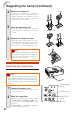
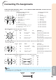
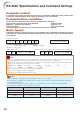
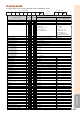
Table Of Contents
- Introduction
- Quick Start
- Setup
- Connections
- Basic Operation
- Useful Features
- Operating with the Remote Control
- Menu Items
- Using the Menu Screen
- Picture Adjustment (“Picture" menu)
- Adjusting the Projected Image (“SCR - ADJ” menu)
- Adjusting the Projector Function (“PRJ - ADJ” menu)
- Auto Search Function
- Auto Sync (Auto Sync Adjustment)
- Auto Power Off Function
- Setting the Confirmation Sound (System Sound)
- Speaker Setting
- Selecting the Transmission Speed (RS-232C)
- Fan Mode Setting
- Checking the Lamp Life Status
- System Lock Function
- Locking the Operation Buttons on the Projector (Keylock Function)
- Troubleshooting with “Help” menu
- Appendix

53
Appendix
Connecting Pin Assignments
COMPUTER-RGB Input/Output
COMPUTER-RGB/COMPONENT INPUT1, 2 and COMPUTER-RGB/COMPONENT OUTPUT Terminals:
15-pin Mini D-sub female connector
1. Video input (red)
2. Video input (green/sync on green)
3. Video input (blue)
4. Not connected
5. Not connected
6. Earth (red)
7. Earth (green/sync on green)
8. Earth (blue)
9. Not connected
10. GND
11. Not connected
12. Bi-directional data
13. Horizontal sync signal: TTL level
14. Vertical sync signal: TTL level
15. Data clock
RS-232C Terminal: 9-pin Mini DIN female connector
Component Input/Output
5
10
15
1
11
6
1. PR (CR)
2. Y
3. PB (CB)
4. Not connected
5. Not connected
6. Earth (PR)
7. Earth (Y)
8. Earth (PB)
9. Not connected
10. Not connected
11. Not connected
12. Not connected
13. Not connected
14. Not connected
15. Not connected
RD
SD
SG
RS
CS
Signal Name
8
9
6
5
21
4
3
7
Pin No.
1.
2.
3.
4.
5.
6.
7.
8.
9.
I/O Reference
Not connected
Connected to internal circuit
Connected to internal circuit
Not connected
Connected to internal circuit
Not connected
Connected to CS in internal circuit
Connected to RS in internal circuit
Not connected
Receive Data
Send Data
Signal Ground
Request to Send
Clear to Send
Input
Output
RS-232C Terminal: 9-pin D-sub male connector of the DIN-D-sub RS-232C adaptor (optional
accessory: AN-A1RS)
RD
SD
SG
RS
CS
Signal NamePin No.
1.
2.
3.
4.
5.
6.
7.
8.
9.
I/O Reference
Not connected
Connected to internal circuit
Connected to internal circuit
Not connected
Connected to internal circuit
Not connected
Connected to CS in internal circuit
Connected to RS in internal circuit
Not connected
Receive Data
Send Data
Signal Ground
Request to Send
Clear to Send
Input
Output
15
69
CD
RD
SD
ER
SG
DR
RS
CS
CI
SignalPin No.
1.
2.
3.
4.
5.
6.
7.
8.
9.
RS-232C Cable recommended connection: 9-pin D-sub female connector
CD
RD
SD
ER
SG
DR
RS
CS
CI
SignalPin No.
1.
2.
3.
4.
5.
6.
7.
8.
9.
51
96
• Depending on the controlling device used, it may be necessary to connect Pin 4 and Pin 6 on the
controlling device (e.g. computer).
Note
Projector
Pin No.
4
5
6
Computer
Pin No.
4
5
6