
XG-C430X/C335X/C330X Operation-Manual GB
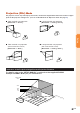
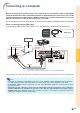
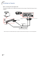
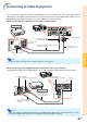
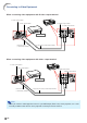
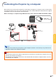
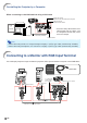
Table Of Contents
- Introduction
- Quick Start
- Setup
- Connections
- Basic Operation
- Turning the Projector On/Off
- Image Projection
- Using the Adjustment Feet
- Correcting Trapezoidal Distortion
- Adjusting the Lens
- Switching the INPUT Mode
- Adjusting the Volume
- Displaying the Black Screen and Turning Off the Sound Temporarily
- Displaying an Enlarged Portion of an Image
- Freezing an Image
- Displaying and Setting the Break Timer
- Switching the Eco/Quiet Mode
- Selecting the Picture Mode
- Resize Mode
- Using the Remote Control as the Wireless Computer Mouse
- Useful Features
- Menu Items
- Using the Menu Screen
- Picture Adjustment (“Picture” menu)
- Computer Image Adjustment (“Fine Sync” menu)
- Using the “Options1” Menu
- Checking the Lamp Life Status
- Setting the Resize Mode
- Adjusting the Image Position
- Keystone Correction
- Setting On-screen Display
- Selecting a Startup and Background Image
- Eco/Quiet Mode Setting
- Auto Power Off Function
- Setting the System Sound
- Selecting the Menu Screen Position
- System Lock Function
- Keylock Function
- Direct Power On Function
- Helpful Functions Set during Installation (“Options2” menu)
- Setting a Password
- If You Forget Your Password
- Speaker Setting
- Audio Output Type Setting
- Reversing/Inverting Projected Images
- Fan Mode Setting
- Monitor Output
- LAN/RS232C
- DHCP Client Setting
- Selecting the Transmission Speed (RS-232C)
- TCP/IP Setting
- Confirming the Network Information for the Projector
- Returning to the Default Settings
- Selecting the On-screen Display Language
- Appendix

-25
Connections
Connecting to Video Equipment
DVI Digital cable
(commercially available)
To audio output
terminals
ø3.5 mm stereo minijack to RCA audio cable
(commercially available)
To DVI output terminal
Video Equipment
To DVI-D input terminal
To AUDIO input terminal
(for COMPUTER/COMPONENT 2, DVI-D)
To audio output terminal
ø3.5 mm minijack to RCA
audio cable (commercially
available)
3 RCA (Component) to
15-pin D-sub cable
(optional: AN-C3CP2)
To component video output terminal
To COMPUTER/
COMPONENT 1 input terminal To AUDIO
input terminal
Video Equipment
The image quality is highest in order of the Component signal, the RGB signal, the S-video signal and the
Video signal. If your audio-visual equipment has a component output terminal or RGB output terminal, use the
COMPUTER/COMPONENT terminal 1 or 2 on the projector for video connection.
When connecting video equipment with a DVI output terminal
Note
• Select the input signal type of the video equipment. See page 45.
When connecting video equipment with component video output terminal
(Connecting to COMPUTER/COMPONENT 1 or 2: The illustration shown below is for the former.)
Note
• When you connect video equipment with a 21-pin RGB output (Euro-scart) to the projector, use a com-
mercially available cable that fits in the projector terminal you want to connect.