TopPage XR-40X/XR-41X/XG-F260X SERVICE MANUAL No. S57J1XR-40X// MULTIMEDIA PROJECTOR MODELS XR-40X XR-41X XG-F260X In the interests of user-safety (Required by safety regulations in some countries) the set should be restored to its original condition and only parts identical to those specified should be used. OUTLINE This Service Manual covers the differences from XR-30X/XG-F210X. For other technical information, refer to the XR30S/XR-30X/XG-F210X (No. S47E3XR-30XS/) Service Manual.
XR-40X/XR-41X/XG-F260X XR-40X OUTLINE AND MODIFIED PARTS LIST Service Manual OUTLINE This Service Manual covers the differences from XR-30X/XG-F210X. For other technical information, refer to the XR-30S/XR-30X/XG-F210X (No. S47E3XR-30XS/) Service Manual. MODIFIED PARTS (XR-30X/XG-F210X → XR-40X/XR-41X/XG-F260X) Ref.No.
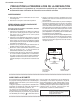
XR-40X/XR-41X/XG-F260X XR-40X SAFETY PRECAUTION Service Manual IMPORTANT SERVICE SAFETY NOTES IMPORTANT SERVICE SAFETY NOTES (for USA) Service work should be performed only by qualified service technicians who are thoroughly familiar with all safety checks and servicing guidelines as follows: Use an AC voltmeter with sensitivity of 5000 ohm per volt., or higher, sensitivity to measure the AC voltage drop across the resistor. All checks must be repeated with the AC plug connection reversed.
XR-40X/XR-41X/XG-F260X PRECAUTIONS A PRENDRE LORS DE LA REPARATION Ne peut effectuer la réparation qu' un technicien spécialisé qui s'est parfaitement accoutumé à toute vérification de sécurité et aux conseils suivants. AVERTISSEMENT Utiliser un voltmètre CA d'une sensibilité d'au moins 5000Ω/V pour mesurer la chute de tension en travers de la résistance.
XR-40X/XR-41X/XG-F260X NOTE TO SERVICE PERSONNEL NOTE POUR LE PERSONNEL D’ENTRETIEN ////////////////////////////////////////////////////////////// UV-RADIATION PRECAUTION ////////////////////////////////////////////////////////////// ////////////////////////////////////////////////////////////// PRECAUTION POUR LES RADIATIONS UV ////////////////////////////////////////////////////////////// The light source, lamp, in the projector emits small amounts of UV-Radiation.
XR-40X/XR-41X/XG-F260X //////////////////////////////////////////////////////////////// //////////////////////////////////////////////////////////////// PRECAUTION POUR LES RADIA TIONS UV (Suite) UV-RADIATION PRECAUTION (Continued) //////////////////////////////////////////////////////////////// //////////////////////////////////////////////////////////////// Lamp Replacement Remplacement de la lampe Note: Remarque: Since the lamp reaches a very high temperature during units operation replacement of th
XR-40X/XR-41X/XG-F260X WARNING: High brightness light source, do not stare into the beam of light, or view directly. Be especially careful that children do not stare directly into the beam of light. WARNING: TO REDUCE THE RISK OF FIRE OR ELECTRIC SHOCK, DO NOT EXPOSE THIS UNIT TO MOISTURE OR WET LOCATIONS. CAUTION The lighting flash with arrowhead within a triangle is intended to tell the user that parts inside the product are risk of electric shock to persons. RISK OF ELECTRIC SHOCK.
XR-40X/XR-41X/XG-F260X Precautions for using lead-free solder Employing lead-free solder • "PWBs" of this model employs lead-free solder. The LF symbol indicates lead-free solder, and is attached on the PWBs and service manuals. The alphabetical character following LF shows the type of lead-free solder. Example: LFa Indicates lead-free solder of tin, silver and copper. Using lead-free wire solder • When fixing the PWB soldered with the lead-free solder, apply lead-free wire solder.
XR-40X/XR-41X/XG-F260X CHAPTER 1. OPERATION MANUAL XR-40X Service Manual [1] Specifications Model Display device Resolution Lens Input terminal Output terminal Control, others XR-40X/XR-41X/XG-F260X 0.55" DLP Chip XGA (1024 x 768) F number Zoom Focus DVI-D (Compatible with HDCP) DVI-I (Compatible with HDCP) RGB/Component (mini D-sub 15 pin) S-Video (mini DIN 4 pin) Video (RCA) Audio (ø3.5 mm stereo minijack) Audio (RCA) RGB/Component (mini D-sub 15 pin) Audio (ø3.
XR-40X/XR-41X/XG-F260X CHAPTER 2. ELECTRICAL ADJUSTMENTService XR-40X Manual [1] ELECTRICAL ADJUSTMENT No. 1 Adjusting point EEPROM initialization Adjusting conditions 1. Turn on the power (with the lamp on) and warm up the set for 15 minutes. 2 Model setting 3 Adjustment of CW index (Process menu) 1. Select the following group and subject. Group: CONFIRM Subject: MODEL 1. Signal input: Send 256 STEP color bar. XGA series (XGA60HZ), 2. Select the following group and subject.
XR-40X/XR-41X/XG-F260X No. 2 Adjusting point Adjustment of Component offset Adjusting conditions 1. Feed 10-step signal with 480P component 100% amplitude. 2. Select the following group and subjects. Group : CONFIRM/AD Subject : C-R-OS C-B-OS (Process GAMMA interlock) 1. Select the following group and subject. Group : CONFIRM/DLP Subject :R-BLK G-BLK B-BLK (Process GAMMA interlock) 1. Feed NTSC 100% wind pattern signal. (Signal with burst) 2. Select the following group and subjects.
XR-40X/XR-41X/XG-F260X No. 16 Adjusting point RS232C operation check 17 Model name and version check 18 Setup guide screen check 19 Delivery settings Adjusting conditions 1. Connect the unit and a PC with the RS232C cable. 1. Select the following group. Group : INFO/VERSION. 1. Turn on the power after making the setup guide display ON setting or factory setting (SS4, etc.). 1. Make the following settings. Destination * Adjusting procedure 1.
XR-40X/XR-41X/XG-F260X [2] Adjustment mode process menu 1st Layer ADJUST CW/Auto KS AD/DLP SS CONFIRM AD DLP VIDEO MODEL CHECK INFO VERSION PATTERN LAMP TEMP/FAN 2nd Layer CW-INDEX CAL K-SENS R-CONT G-CONT B-CONT R-GAIN G-GAIN B-GAIN SS1 SS2 SS3 SS4 SS5 SS6 R-BRIGHT G-BRIGHT B-BRIGHT C-R-OS C-B-OS R-BLK G-BLK B-BLK S-R-OS S-G-OS S-B-OS V-CONT V-BRIGHT V-COLOR V-HUE V-R-OS V-G-OS V-B-OS OFFSET-MODE OFFSET-CONT OFFSET-BRI MODEL-SELECT LED-CHK TEMP-OFF MODEL VER.
XR-40X/XR-41X/XG-F260X 1. Adjustment of ballast unit output power (lamp power) 1. List of parts requiring adjustment When replacing the following parts, adjust the ballast unit output power (lamp power). 1 2 3 4 5 Part name Cement resistor Ballast Control PWB Ballast microprocessor 5V regulator Ballast Switching Control Ref No. R923 —— IC7707 IC7704 IC7701 Part code RR-FZA002WJZZ DUNTKE150WEF0 RH-iXC103WJZZQ VHiTA78L05F-1Y VHiM51995AF-1Y 2.
XR-40X/XR-41X/XG-F260X PartsGuide PARTS GUIDE MULTIMEDIA PROJECTOR MODELS XR-40X XR-41X XG-F260X Note: The reference numbers on the PWB are arranged in alphabetical order. CONTENTS [1] PRINTED WIRING BOARD ASSEMBLIES [2] CABINET AND MECHANICAL PARTS [3] OPTICAL MECHANISM PARTS [4] SUPPLIED ACCESSORIES [5] PACKING PARTS (NOT REPLACEMENT ITEM) [6] SERVICE JIGS AND EQUIPMENT (USE FOR SERVICING) Parts marked with " " are important for maintaining the safety of the set.
XR-40X/XR-41X/XG-F260X NO. PARTS CODE PRICE NEW PART RANK MARK DELIVERY DESCRIPTION [1] PRINTED WIRING BOARD ASSEMBLIES N DSETUE149FMG0 BZ N J N Not Available - N - N N N N N N DUNTKE150WEF0 DUNTKE151WEF0 DUNTKE152WEF0 DUNTKE153FMF2 DUNTKE153FMF3 DUNTKE154WEF0 BW AY AY DA DB CN N N N N N N J J J J J J BALLAST POWER Ass'y (with Ballast Control Unit) BALLAST POWER Unit Order the BALLAST POWER Ass'y (DSETUE149FMG1) when replacing ballast power unit (DUNTKE149WEF1).
XR-40X/XR-41X/XG-F260X [2] CABINET AND MECHANICAL PARTS 1-4 18 10 1 10 30 1-3 40 42 25 10 1-1 31 40 19 1-2 1-5 29 10 17 23 43 24 45 6 15 12 39 22 44 32 39 14 33 2-6 38 2-4 8 2-10 2-11 40 34 9 40 2-5 2-3 27 2-2 2 16 4 41 5 40 2-1 2-1-3 2-9 2-8 37 2-1-1 26 2-1-2 3 2-7
XR-40X/XR-41X/XG-F260X NO.
XR-40X/XR-41X/XG-F260X [3] OPTICAL MECHANISM PARTS 11 11 11 4-33 13 13 11 13 20 13 4-33 4-11 21 4-33 7 28 4-27 4-33 35 4-33 4-25 36 4-16 4-24 4-36 4-33 4-29 4-34 4-13 4-34 4-8 4-33 4-33 4-33 4-12 4-33 4-33 4-30 4-31 4-31 4-33 4-31 4-31 4-5 4-26 4-6 4-33 4-31 4-28 4-31 4-18 4-31 4-33 4-7 4-20 4-21 4-15 4-33 4-22 4-31 4-33 4-17 4-2 4-32 4-23 4-1 4-32 4-32 4-4 4-3 4-35 4-35 4-19 4-33 4-14 4-33 4-33 4-33 4-10 4-9 4-33 4-33 5
XR-40X/XR-41X/XG-F260X NO.
XR-40X/XR-41X/XG-F260X [4] SUPPLIED ACCESSORIES X1 X3 X2 X4 X6 X5 X10 X12 NO.
XR-40X/XR-41X/XG-F260X [5] PACKING PARTS (NOT REPLACEMENT ITEM) For XR-40X For XR-41X/XG-F260X S6 S6 S7 S3 S8 S1 S3 S8 S10 S4 S5 S11 S9 S11 S2 8
XR-40X/XR-41X/XG-F260X NO. PARTS CODE PRICE NEW PART RANK MARK DELIVERY DESCRIPTION [5] PACKING PARTS (NOT REPLACEMENT ITEM) S1 S2 S2 S2 S3 S4 S5 S6 S7 S8 S9 S9 S10 S11 SPAKAA329WJZZ SPAKCD451WJZZ SPAKCD452WJZZ SPAKCD508WJZZ SPAKFB224WJZZ SPAKPA869WJZZ SPAKXB477WJZZ SSAKA0160CEZZ SSAKAA097WJZZ TLABV0003SEZZ TLABVA333WJZZ TLABVA493WJZZ TLABZA610WJZZ TLABZA957WJZZ - N N N N N N N N N - Packing Add.
XR-40X/XR-41X/XG-F260X COPYRIGHT © 2007 2006 BY SHARP CORPORATION ALL RIGHTS RESERVED. No Part of this publication may be reproduced, stored in a retrieval system, or transmitted in any from or by any means, electronic, mechanical, photocopying , recording, or otherwise, without prior written permission of the publisher. TQ2222-S YK.