
Programming instructions

Basic Components
Multisim Component Reference Guide 2-22 ni.com
These expressions are derived by applying appropriate numerical integration to the
characteristic equation of the capacitor.
2.7.4 AC Frequency Model
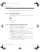
For the small-signal analysis, the capacitor is modeled by an impedance whose imaginary
component is equal to:
where:
f = frequency of operation
C = capacitance value
2.7.5 Changing a Placed Capacitor’s Value
To change the value, and other parameters of a placed capacitor:
1. Double-click on the capacitor and select the Value tab.
2. Select the desired capacitance from the Capacitance(C) list. If it is not there, type the value
you want.
3. Select the desired tolerance from the Tolerance list, or type in a value.
4. Optionally, enter information in the Component Type (for example, ceramic) and
Hyperlink fields.
5. Optionally, enable the Additional SPICE Simulation Parameters field described below:
•
Initial Conditions checkbox — enable and then enter an initial voltage charge for the
capacitor.
6. Optionally, change the Layout Settings as described below:
•
Edit Footprint button — click to display the Edit Footprint dialog box where you can
select a new
Footprint and Manufacturer.
Note For information on placing capacitors, and information on how to edit footprints, refer
to the
Multisim User Guide or the Multisim helpfile.
1
2
π
fC
ComponentRef.book Page 22 Thursday, December 7, 2006 10:12 AM