
Programming instructions

Basic Components
Multisim Component Reference Guide 2-2 ni.com
2.2.1 Rated 555 Timer
The 555 timer is an IC chip that is commonly used as an astable multivibrator, a monostable
multivibrator or a voltage-controlled oscillator. The 555 timer consists basically of two
comparators, a resistive voltage divider, a flip-flop and a discharge transistor. It is a two-state
device whose output voltage level can be either high or low. The state of the output can be
controlled by proper input signals and time-delay elements connected externally to the 555
timer.
Note Refer to the Component Reference Guide for a more detailed discussion of the
555 timer.
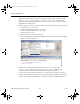
To adjust the component’s tolerances:
1. Double-click on the placed component and click the Value tab.
2. Change the following values as desired:
•
Animation Delay Factor — increase this number to slow the speed of animation of the
symbol blowing. This is not a real-time value.
•
Maximum Supply Voltage — the maximum supply voltage allowed. If this is exceeded
during simulation, the timer’s VCC pin blows.
•
Maximum Output Current — the maximum output current allowed. If this is exceeded
during simulation, the timer’s OUT pin blows.
3. Click OK.
ComponentRef.book Page 2 Thursday, December 7, 2006 10:12 AM