
Programming instructions


Voltage Slew Rate Block
National Instruments Corporation 1-43 Multisim Component Reference Guide
1.38 Voltage Slew Rate Block
This component limits the absolute slope of the output, with respect to time, to some
maximum or value. You can accurately model actual slew rate effects of over-driving an
amplifier circuit by cascading the amplifier with this component. Maximum rising and falling
slope values are expressed in volts per second.
The slew rate block will continue to raise or lower its output until the difference between
input and output values is zero. After, it will resume following the input signal unless the
slope again exceeds its rise or fall slope limits.
This component provides for introduction of selectable rising and falling slew rates (rise and
fall times on a pulse waveform) for analysis of pulse and analog circuits.
With an ideal pulse or analog input to block the effect of slew rate on a logic circuit or analog
amplifier, (discrete component or op-amp) output may be investigated.
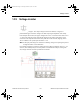
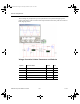
In the example shown below, the function generator may be set for either square wave or sine
wave output.
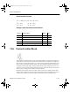
A slew rate of 8000V/sec for rising slope and 6000V/sec for falling slope shows as rise and
fall time on an ideal 80Hz. square wave input. Signal degradation as a result of slew rate
occurs when frequency is increased.
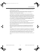
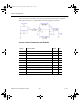
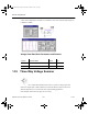
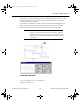
Switching the function generator to sine wave output 60 Hz. does not result in distortion.
However, as frequency is increased, slew rate distortion on a sine wave will become evident at
200 Hz. and above. As frequency is increased, the sine wave deteriorates to a triangle shape.
ComponentRef.book Page 43 Thursday, December 7, 2006 10:12 AM