
Programming instructions


Voltage-Controlled Limiter
National Instruments Corporation 1-41 Multisim Component Reference Guide
1.37 Voltage-Controlled Limiter
A voltage “clipper”. This component is a single input, single output function. The output is
restricted to the range specified by the output lower and upper limits. Output smoothing
occurs within the specified range. The voltage-controlled limiter will operate in DC, AC and
transient analysis modes.
The component tests the values of the upper and lower limit control inputs to make sure that
they are spaced far enough apart to guarantee the existence of a linear range between them.
The range is calculated as the difference between (upper limit control input (U) - VoUD -
ULSR) and (lower limit control input (L) + VoLD + ULSR) and must be greater than or equal
to zero.
The limiting levels may be individually set at fixed values or one or both limiting levels may
be controlled by a variable voltage, depending on the desired application.
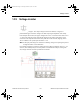
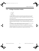
In the circuit shown below, the upper voltage limit is set by adjusting the potentiometer
supplying the Upper terminal on the VCL. The lower voltage limit is set by adjusting the
potentiometer supplying the Lower terminal on the VCL. The potentiometers are adjusted by
pressing U or SHIFT-U for the upper limit and L or SHIFT-L for the lower limit.
ComponentRef.book Page 41 Thursday, December 7, 2006 10:12 AM