
Programming instructions


Current Limiter Block
National Instruments Corporation 1-39 Multisim Component Reference Guide
specified by either ISrcL or ISnkL. The latter mimics the current limiting behavior of many
operational amplifier output stages.
During operation, the output current is reflected either in the positive or the negative power
supply inputs, depending on the polarity of the output current. Thus, realistic power
consumption as seen in the supply rails is modeled.
ULSR controls the voltage below positive input power and above negative input power
beyond which V
eq
= k (input voltage + Off) is smoothed. ISrcSR specifies the current below
ISrcL at which smoothing begins, and specifies the current increment above zero input current
at which positive power begins to transition to zero. ISnkSR serves the same purpose with
respect to ISnkL and negative power. VDSR specifies the incremental value above and below
(V
eq
- output voltage) = 0 at which output resistance will be set to Rsrc and Rsnk, respectively.
For values of (V
eq
- output voltage) less than VDSR and greater than -VDSR, output
resistance is interpolated smoothly between Rsrc and Rsnk.
The current limiter block is also a representation of an operational amplifier with respect to
the sourcing and sinking of current at the output and supply terminals.
If the current being sinked/sourced to the load is less than the rated maximum, as determined
from rated maximum sink/source specifications for a particular opamp, operation of the
opamp circuit will be as expected.
If the current to be sinked/sourced is greater than the rated maximum, as determined by a
larger than normal input to the opamp circuit, the current limiter will limit current to the
specified safe maximum value, thus protecting the opamp and associated circuitry from
damage.
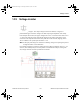
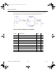
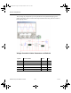
In the example circuit shown below, the sink and source current limits are set to 2 mA and the
circuit gain (K) is set to 1. For this case, output current should then be Iload = Vin*K/Rload.
The switch, activated by pressing S, applies either a positive or negative input to the 'op-amp'
circuit. These input levels are such that the output current would be in excess of the rated
value of 2.0mA. The current limit function limits the source or sink output to 2.0 mA.
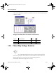
If the input levels are reduced to 2V or less, then the output current will be as expected at Vin/
Rload.
ComponentRef.book Page 39 Thursday, December 7, 2006 10:12 AM