
Programming instructions

Source Components
Multisim Component Reference Guide 1-34 ni.com
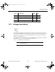
Characteristic Equation
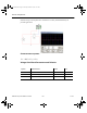
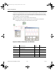
Voltage Integrator Parameters and Defaults
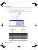
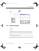
1.33.1 Investigations
1. In the initial circuit, the input signal is symmetrical (+/- 5V) about the zero axis and the
integrator output is zero for sine, square and triangle waveforms.
2. To make the waveforms unsymmetrical about the zero axis use the OFFSET control on the
function generator. Setting the OFFSET equal to the AMPLITUDE setting will reference
the input to ground (0V).
In this case, the output is always positive. When output is high, “area” is continually added.
Output will rise indefinitely.
Symbol Parameter Name Default Unit
VIoff Input offset voltage 0 V
KGain 1 V/V
Vl Output voltage lower limit -1e+12 V
Vu Output voltage upper limit 1e+12 V
Vs Upper and lower smoothing range 1e-06 V
VOic Output initial conditions 0 V
()
Vt KVtV dtV
out i Ioff Oic
t
() ()=++
∫
0
ComponentRef.book Page 34 Thursday, December 7, 2006 10:12 AM