
Programming instructions

Source Components
Multisim Component Reference Guide 1-28 ni.com
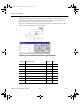
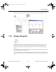
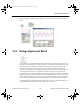
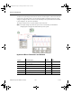
In the example shown below, the transfer function for a simple first order low pass filter is
used. Only the numerator and denominator constants A0 and B0 are required in this case.
These are equal to two pi times the cutoff frequency (first pole).
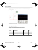
The cursor on the Bode Plotter may be used to confirm first order performance with -3dB at
10kHz. and rolloff of 6dB per octave above 20kHz.
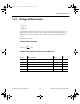
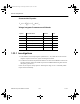
Transfer Function Block Parameters and Defaults
Symbol Parameter Name Default Unit
VIoff Input voltage offset 0 V
KGain 1V/V
VINT Integrator stage initial conditions 0 V
w Denormalized corner frequency 1 -
A3 Numerator 3rd order coefficient 0 -
A2 Numerator 2nd order coefficient 0 -
A1 Numerator 1st order coefficient 0 -
A0 Numerator constant 1 -
ComponentRef.book Page 28 Thursday, December 7, 2006 10:12 AM