
Programming instructions

Misc. Components
Multisim Component Reference Guide 13-12 ni.com
The lossy model also models resistive losses in the line along with the characteristic
impedance and propagation delay properties of the transmission line.
This is a two-part convolution model for single-conductor lossy transmission lines. The
uniform constant-parameter distributed transmission line model can be used to model the
following types of lines:
• RLC (uniform transmission lines with series loss only)
• RC (uniform RC lines)
• LC (lossless transmission lines)
• RG (distributed series and parallel conductance).
13.8.1 Model
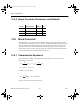
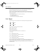
The characteristic of a lossy transmission line is modeled by the Telegrapher Equations:
with the following boundary and initial conditions:
v (0,t) = v
1
(t), v (l,t) = v
2
(t)
i (0,t) = i
1
(t), i (l,t) = -i
2
(t)
v (x,0) = v
0
(x), i (x,0) = i
0
(x)
where the transmission line stretches from x coordinates 0 to l
l = line length
V(x,t) = voltage at point x at time t
i (x,t) = current in the positive x direction at x at time t
v (0,t) = voltage at point 0 at time t
i (0,t) = current in the positive x direction at 0 at time t
v (x,0) = voltage at point x at time 0
i (x,0) = current in the positive x direction at x at time 0.
The set of equations is first transformed into a pair of coupled ordinary differential equations
in x and s using the Laplace transformation. The equations are then reformulated for
numerical convolution. Finally, inverse Laplace transforms are taken to return them to the
time-domain form.
∂
∂
∂
∂
∂
∂
∂
∂
v
x
L
i
t
Ri
i
x
C
v
t
Gv
=− +
=− +
()
()
ComponentRef.book Page 12 Thursday, December 7, 2006 10:12 AM