
Programming instructions

Buck Converter
National Instruments Corporation 13-9 Multisim Component Reference Guide
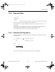
For the DCM:
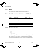
For the critical condition between the CCM and DCM of operation:
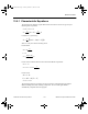
For the CCM:
The averaging behavior governed by the above equations is modeled using the built-in
Multisim analog behavioral modeling components. The AC small-signal model is
automatically computed inside the program.
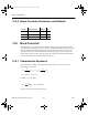
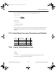
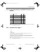
13.6.2 Buck Converter Parameters and Defaults
()
DD
VV
V
V
IDVV
DD
LF
i
l
LD i
s
2
0
0
0
2
0
2
=
−
=
=−
+
∗∗
DD
II
VV
LF
LD Lcrit
i
s
2
0
1
2
=−
==
−
∗∗
DD
VDVV DV
II I
Li o
LLcritLL
2
02
1=−
=−−∗
=+
()
Symbol Parameter Name Default Unit
L Filter inductance 500 µH
R Filter inductor ESR 5 mΩ
Fs Switching frequency 50 kHz
ComponentRef.book Page 9 Thursday, December 7, 2006 10:12 AM