
Programming instructions

Misc. Components
Multisim Component Reference Guide 13-8 ni.com
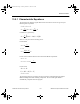
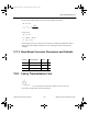
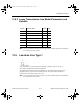
13.5.2 Boost Converter Parameters and Defaults
13.6 Buck Converter
This component is an averaging circuit model that models the averaging behavior of a step-
down DC-to-DC switching converter. It is based on a unified behavioral model topology. The
topology models both small-signal and large-signal characteristics of this converter power
stage. The model can be used to simulate DC, AC and large-signal transient responses of
switched-mode power supplies, operating in both the continuous and discontinuous inductor
current conduction modes (CCM and DCM, respectively).
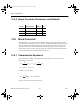
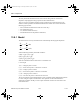
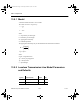
13.6.1 Characteristic Equations
The averaging DC and large-signal characteristics of a Buck converter are given by the
following sets of equations:
in which I
LL
is governed by:
where D = duty ratio of the switching device.
Symbol Parameter Name Default Unit
L Filter inductance 500 µH
R Filter inductor ESR 10 mΩ
Fs Switching frequency 50 kHz
I
D
DD
II
D
DD
I
III I
iLLLDL
oLLLDL
=
+
∗+ =
+
∗
=− + =−
22
()
()
[]
I
L
DV V DV dt
LL i o
o
t
=−−
∫
1
20
()
ComponentRef.book Page 8 Thursday, December 7, 2006 10:12 AM