
Programming instructions
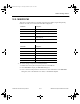

Misc. Components
Multisim Component Reference Guide 13-2 ni.com
oriented crystallites of varying size. The piezoelectric but not the ferroelectric property of the
ceramic materials of the PZT family is made use of in transducer applications, such as
ultrasonic echo ranging (sonar), medical diagnostic ultrasound and nondestructive testing
system devices.
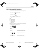
13.2 DC Motor
The component is a universal model of an ideal DC motor which can be used to model the
behavior of a DC motor excited in parallel, in series or separately. The excitation type of the
component is determined by the interconnection of the terminals between field windings
(terminals 1 and 2) and armature windings (terminals 3 and 4).
To excite the DC motor in parallel, connect the positive terminal of a DC source to terminals 2
and 4; then connect the negative terminals of the DC source to terminals 1 and 3. To excite the
DC motor in series, connect terminal 2 to terminal 3 (use a connector); then connect the
positive terminal of a DC source to terminal 4 and connect the negative terminal of the DC
source to terminal 1. To excite the DC motor separately, connect a DC source to terminals 2
and 1 (positive and negative, respectively); then connect another DC source to terminals 4 and
3 (positive and negative, respectively).
Terminal 5 is the DC motor’s output. The output is the motor’s rpm value.
To display this value:
• attach a voltmeter to terminal 5 (connect the other side of the voltmeter to ground) and
simulate
or
• attach the oscilloscope to terminal 5 and simulate (the rpm value is the voltage that
appears)
or
• attach a connector to terminal 5, then choose an appropriate analysis from the Analysis
menu (for example, if you choose Analysis/DC Operating Point, the rpm value is the
voltage at the connector).
This component connects the electrical and mechanical parts of a servo-system. Input to the
motor is electrical while output is mechanical.
ComponentRef.book Page 2 Thursday, December 7, 2006 10:12 AM