
Programming instructions


SMPS Average Virtual
National Instruments Corporation 12-21 Multisim Component Reference Guide
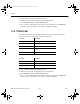
12.2.7 FLYBACKCCM
This is the Ripley's averaged model (no switching component) of a flyback converter in a
current mode controlled configuration. This is an improved model over FLYBACKCM, but it
must operate in continuous conduction mode.
To view or change a component’s model parameters:
1. Double-click on the placed component and select the Valu e tab.
2. Click Edit Model to display the Edit Model dialog box.
3. View or edit the model parameters as desired. For more information on the Edit Model
dialog box, refer to the Multisim User Guide, or the Multisim helpfile.
Pin Name Description
VIN Input voltage
VOUT Output voltage
CONTROL Feedback voltage error
GND Ground
D Duty cycle setting
Parameter Description
FS Switching frequency
L Main inductor
RS Equivalent series resistance of output
capacitor
MC Compensation ramp (in V/s)
RI Current sense resistor
VOUT Output voltage
VIN Input voltage
RL Load resistor
ComponentRef.book Page 21 Thursday, December 7, 2006 10:12 AM