
Programming instructions


SMPS Transient Virtual
National Instruments Corporation 12-11 Multisim Component Reference Guide
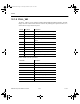
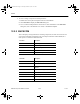
Generic PWM controller parameters:
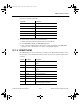
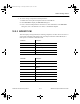
Internal error amplifier parameters:
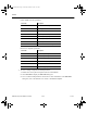
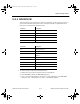
To view or change a component’s model parameters:
1. Double-click on the placed component and select the Valu e tab.
2. Click Edit Model to display the Edit Model dialog box.
3. View or edit the model parameters as desired. For more information on the Edit Model
dialog box, refer to the Multisim User Guide, or the Multisim helpfile.
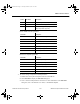
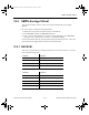
4 FB Output voltage feedback input
5 ISENSE Switch current sensing (for current limit)
6 VOSC Oscillator ramp signal output (provided for
ramp compensation purposes)
Parameter Description
REF Internal reference voltage
PERIOD Switching period
DUTYMAX Maximum duty cycle
RAMP Ramp amplitude for compensation
VOUTHI Driver output voltage high
VOUTLO Driver output voltage low
ROUT Driver output resistor
Parameter Description
VHIGH Maximum output voltage
VLOW Minimum output voltage
ISINK Current sink capability
ISOURCE Current source capability
POLE First pole in Hertz
GAIN DC open-loop gain (default = 90 dB)
Pin No. Pin Name Description
ComponentRef.book Page 11 Thursday, December 7, 2006 10:12 AM