
Programming instructions


Power
Multisim Component Reference Guide 12-10 ni.com
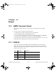
Internal error amplifier parameters:
To view or change a component’s model parameters:
1. Double-click on the placed component and select the Value tab.
2. Click Edit Model to display the Edit Model dialog box.
3. View or edit the model parameters as desired. For more information on the Edit Model
dialog box, refer to the Multisim User Guide, or the Multisim helpfile.
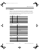
12.1.7 FULL_CM
The FULL_CM is a generic model for Current Mode Full-bridge PWM controllers. The full-
bridge converter is derived from the buck converter. By utilizing four operated switches, it is
able to deliver a larger amount of power.
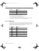
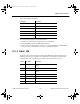
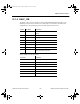
Parameter Description
VHIGH Maximum output voltage
VLOW Minimum output voltage
ISINK Current sink capability
ISOURCE Current source capability
POLE First pole in Hertz
GAIN DC open-loop gain (default = 90 dB)
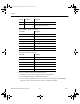
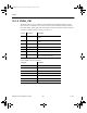
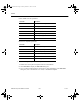
Pin No. Pin Name Description
1 OUT1 PWM signal Output 1 (Switch1 control signal)
8 GNF1 Voltage reference for OUT1
7 OUT2 PWM signal Output 2 (Switch2 control signal)
2 GND Ground (Voltage reference for OUT2 and
OUT4)
9 OUT3 PWM signal Output 3 (Switch3 control signal)
16 GNF3 Voltage reference for OUT3
15 OUT4 PWM signal Output 4 (Switch4 control signal)
3 COMP Error amplifier output
ComponentRef.book Page 10 Thursday, December 7, 2006 10:12 AM