
Programming instructions

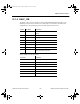

SMPS Transient Virtual
National Instruments Corporation 12-3 Multisim Component Reference Guide
12.1.2 PWMVM
This device is a generic voltage mode PWM controller. In the PWMVM, an error voltage is
compared to a sawtooth ramp to control the duty cycle of the power switch. The higher the
error voltage, the longer the duty cycle (i.e., the on-time of power switch). The error voltage is
derived in a feedback system from the error amplifier that amplifies the difference between
the output voltage and the reference voltage.
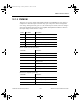
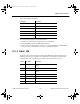
Generic PWM controller parameters:
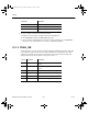
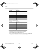
Internal error amplifier parameters:
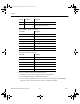
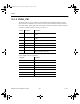
Pin No. Pin Name Description
1 OUT PWM signal Output (MOSFET switch signal)
2 GND Ground
3 COMP Error amplifier output
4 FB Output voltage feedback input
5 ISENSE Switch current sensing (for current limit)
Parameter Description
REF Internal reference voltage
PERIOD Switching period
DUTYMAX Maximum duty cycle
IMAX Maximum voltage on (external) current
sensing resistor
VOUTHI Driver output voltage high
VOUTLO Driver output voltage low
ROUT Driver output resistor
Parameter Description
VHIGH Maximum output voltage
VLOW Minimum output voltage
ISINK Current sink capability
ComponentRef.book Page 3 Thursday, December 7, 2006 10:12 AM