
Programming instructions


National Instruments Corporation 12-1 Multisim Component Reference Guide
Chapter 12
Power
12.1 SMPS Transient Virtual
This component family contains a variety of transient switched-mode power supplies
(SMPS).
To view or change a component’s model parameters:
1. Double-click on the placed component and select the Valu e tab.
2. Click Edit Model to display the Edit Model dialog box.
3. View or edit the model parameters as desired. For more information on the Edit Model
dialog box, refer to the Multisim User Guide, or the Multisim helpfile.
For more information about the components described in the following sections, refer to the
Switch-Mode Power Supply SPICE Cookbook, McGraw-Hill, 2001.
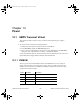
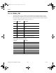
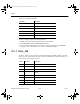
12.1.1 PWMCM
This is a generic current mode PWM controller. The PWMCM uses an error voltage to
directly control the peak current of the power switch. The error voltage is derived in the
feedback system from the error amplifier that amplifies the difference between the output
voltage and the reference voltage.
Pin No. Pin Name Description
1 OUT PWM signal Output (MOSFET switch signal)
2 GND Ground
3 COMP Error amplifier output
4 FB Output voltage feedback input
ComponentRef.book Page 1 Thursday, December 7, 2006 10:12 AM