
Programming instructions


Indicators
Multisim Component Reference Guide 11-8 ni.com
Bargraph Display Parameters and Defaults
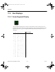
11.6.1 Decoded Bargraph Display
This display consists of 10 LEDs arranged side by side, just like the regular bargraph display.
The difference is that the decoded bargraph display already has the decoding circuitry built-in
so that it only requires the voltage to be measured as an input to the display. The circuitry
inside decodes the voltage and lights up the appropriate number of LEDs, depending on the
voltage level.
The decoded bargraph display also offers a very high resistance to the input voltage. The
minimum voltages required for the lowest LED and the highest LED are set in the Value tab
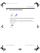
of the Circuit/Component Properties dialog box. The voltage at which each LED (from
lowest to highest) lights up is given by the formula:
where:
n = 1, 2, ..., 10 (the number of the LED)
Other terms in this formula are defined in the table below.
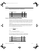
Decoded Bargraph Display Parameters and Defaults
Symbol Parameter Name Default Unit
Vf Forward voltage drop 2 V
If Forward current at which Vf is measured 0.03 A
Ion Forward current 0.01 A
Symbol Parameter Name Default Unit
Vl Minimum turn-on voltage required for
the lowest segment
1V
Vh Minimum turn-on voltage required for
the highest segment
10 V
()
()
VV
VV
n
on l
hl
=+
−
∗−
9
1
ComponentRef.book Page 8 Thursday, December 7, 2006 10:12 AM