
Programming instructions


National Instruments Corporation 11-1 Multisim Component Reference Guide
Chapter 11
Indicators
11.1 Voltmeter
The voltmeter offers advantages over the multimeter for measuring voltage in a circuit. You
can use an unlimited number of voltmeters in a circuit and rotate their terminals to suit your
layout.
Resistance (1.0 Ω - 999.99 TW)
The voltmeter is preset to a very high resistance (1 MΩ(+)) which generally has no effect on
a circuit. If you are testing a circuit that itself has very high resistance, you may want to
increase the voltmeter’s resistance to get a more accurate reading. (However, using a
voltmeter with very high resistance in a low-resistance circuit may result in a mathematical
round-off error.)
Mode (DC or AC)
The voltmeter can measure DC or AC voltage. In DC mode, any AC component of the signal
is eliminated so that only the DC component of the signal is measured. In AC mode, any DC
component is eliminated so that only the AC component is measured. When set to AC, the
voltmeter displays the root-mean-square (RMS) value of the signal.
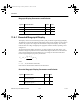
Connecting a Voltmeter
Connect the voltmeter in parallel with the load, attaching the probes to connectors on either
side of the load you want to measure. When a circuit is activated and its behavior is simulated,
the voltmeter displays the voltage across the test points. (The voltmeter may also display
interim voltages before the final steady-state voltage is reached.)
Note If a voltmeter is moved after the circuit has been simulated, activate the circuit again to
get a reading.
ComponentRef.book Page 1 Thursday, December 7, 2006 10:12 AM