
Programming instructions
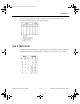

Phase-Locked Loop
National Instruments Corporation 10-5 Multisim Component Reference Guide
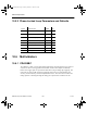
input reference signal and the VCO output signal. The output of the phase detector is input to
the low-pass filter, which removes the high-frequency noise and outputs a DC voltage. The
VCO converts the DC voltage into its corresponding frequency signal.
10.5.1 Characteristic Equation
The phase detector is modeled by:
The low-pass filter is modeled by a simple passive RC low-pass filter, that is, a resistor and a
capacitor, where R is 3.6 kohm, and:
The voltage-controlled oscillator (VCO) is modeled by:
where:
f
i
= input frequency
f
p
= low-pass filter pole location
f
o
= VCO output frequency
f
c
= VCO free-running frequency
V
d
= phase detector output DC voltage
V
o
= VCO output voltage
K
o
= VCO conversion gain
K
d
= phase detector conversion gain
ϕ
i
= input signal phase
ϕ
o
= VCO output phase
()
VK
f
tdt
dd io
i
=∗ −
=∗
∫
sin
()
ϕϕ
ϕ
π
2
1
C
fR
p
=
∗∗
1
2
π
ft f KVt
ftdt
ococ
oo
() ()
()
=+∗
=∗
∫
ϕπ
2
ComponentRef.book Page 5 Thursday, December 7, 2006 10:12 AM