
Programming instructions

Mixed Components
Multisim Component Reference Guide 10-4 ni.com
10.4 Mono Stable
This component produces an output pulse of a fixed duration in response to an “edge” trigger
at its input. The length of the output pulse is controlled by the timing RC circuit connected to
the monostable multivibrator.
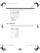
10.4.1 Model
A monostable multivibrator has two digital inputs: A1 and A2. The multivibrator can be
triggered by a positive edge of digital signal at A1 or a negative edge at A2. Once triggered, it
ignores further inputs.
An RC combination connected to RT/CT and CT pins controls the duration of the pulse
produced by the monostable at Q. A complementary output is produced at W.
To operate the monostable, the following connections may be used:
• Connect a series resistor (R) and capacitor (C) to the CT input.
• Connect the junction of the R and C to the RT/CT.
• Connect V
CC
to a voltage source.
The output Q will give a pulse of duration 0.0693*R*C when either a positive clock edge is
given to A1 or a negative edge is given to A2.
The threshold voltage (at which triggering starts) can be changed by modifying the model.
10.5 Phase-Locked Loop
This component models the behavior of a phase-locked loop circuit, which is a circuit that
contains an oscillator whose output phase and frequency are steered to keep it synchronized
with an input reference signal.
A phase-locked loop circuit is composed of three functional blocks: a phase detector, a low-
pass filter and a voltage-controlled oscillator (VCO). The phase detector behaves as an analog
multiplier. It outputs a DC voltage which is a function of the phase difference between the
ComponentRef.book Page 4 Thursday, December 7, 2006 10:12 AM