
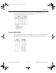
Programming instructions

Timer
National Instruments Corporation 10-3 Multisim Component Reference Guide
10.3 Timer
The 555 timer is an IC chip that is commonly used as an astable multivibrator, a monostable
multivibrator or a voltage-controlled oscillator. The 555 timer consists basically of two
comparators, a resistive voltage divider, a flip-flop and a discharge transistor. It is a two-state
device whose output voltage level can be either high or low. The state of the output can be
controlled by proper input signals and time-delay elements connected externally to the 555
timer.
10.3.1 Model
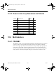
The resistive voltage divider is used to set the voltage comparator levels. All three resistors
are of equal value. The upper comparator has a reference voltage of 2/3 V
cc
and the lower
comparator has a reference of 1/3 V
cc
. The comparator’s output controls the state of the flip-
flop and hence the output. When the trigger voltage goes below 1/3 V
cc
, the output of the
lower comparator goes high, and the flip-flop sets. The output thus jumps to a high level. The
threshold input is normally connected to an external RC timing network. When the external
voltage exceeds 2/3 V
cc
, the upper comparator’s output goes high and resets the flip-flop,
which in turn switches the output back to the low level. When the device output is low, the
discharge transistor, Q, is turned on and provides a path for the discharge of the external
timing capacitor.
This basic operation allows the timer to be configured with external components as an
oscillator, a monoshot or a time-delay element.
ComponentRef.book Page 3 Thursday, December 7, 2006 10:12 AM