
Programming instructions
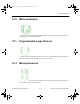

Mixed Components
Multisim Component Reference Guide 10-2 ni.com
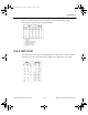
D0 through D7. These are tri-stated outputs pins which may be enabled by pulling the OE pin
high.
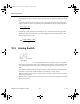
The output at the end of the conversion process is the digital equivalent of the analog input
voltage. The discrete value corresponding to the quantized level of input voltage is given by:
Note that the output described by this formula is not a continuous function of input voltage.
The discrete value is then encoded into the binary digital form at pins D0 through D7. The
binary output is thus given by:
10.2 Analog Switch
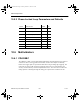
This switch is a resistor that varies logarithmically between specified values of a controlling
input voltage. Note that the input is not internally limited. Therefore, if the controlling signal
exceeds the specified Coff or Con values, the resistance may become excessively large or
small.
The voltage controlled switch has a function similar to that performed by a mechanical On/
Off switch except that the On/Off conditions are selected by a control voltage.
When the control voltage is below a selected value, the switch is off and the input and output
signals are disconnected.
When the control voltage is above the selected value, the switch is on and the input and output
signals are connected.
input voltage
V
fs
*256
BIN
input voltage
V
fs
*256
ComponentRef.book Page 2 Thursday, December 7, 2006 10:12 AM