
Programming instructions

Source Components
Multisim Component Reference Guide 1-10 ni.com
which is the ratio of the output current to the input current. The current gain can have any
value from mA/A to kA/A.
1.16 Voltage-Controlled Sine Wave
This oscillator takes an input AC or DC voltage, which it uses as the independent variable in
the piecewise linear curve described by the (control, frequency) pairs. From the curve, a
frequency value is determined, and the oscillator outputs a sine wave at that frequency. When
only two co-ordinate pairs are used, the oscillator outputs a linear variation of the frequency
with respect to the control input. When the number of co-ordinate pairs is greater than two,
the output is piecewise linear. You can change the peak and valley values of the output sine
wave by resetting the Output peak high value and Output peak low value on the model
parameter dialog box.
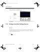
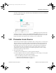
Example
The example shows a sine wave generator with output frequency determined by a control
voltage.
Control voltage may be DC, controlled by a potentiometer, as is the case for many signal
generators and function generators, or may be the output from a PLL that determines a precise
frequency.
Control voltage may be a continuous variable of any desired shape as required in sweep
generators and spectrum analysers.
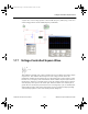
In the example shown below, the VCO parameters are set so that control voltage of 0V
produces an output frequency of 100Hz and a control voltage of 12V produces an output
frequency of 20KHz.
F
I
I
OUT
IN
=
ComponentRef.book Page 10 Thursday, December 7, 2006 10:12 AM