
Programming instructions
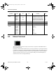


Advanced Peripherals
Multisim Component Reference Guide 8-6 ni.com
Features
• Supports three modes: Graphics, Text, Graphic + Text
• Up to 256 x 256 pixel display resolution
• Displays in two colors
• Display columns in Text mode: 32 - 50
• Display lines in Text mode: 2 - 32
• Font Width: 5, 6, 7, 8
• Font Height: 8
• Maximum number of the characters is 256; 0 – 127 in ROM area (character code 0101)
• 20 pins with 8 data pins (Pin definition is based on Futurlec T6963 LCD)
• Command system based on Toshiba T6963C
• Single-scan memory mode
• Internal memory RAM: 12kB (minimum required size, T6963 allows maximum of 64 kB)
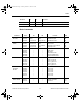
Pin Descriptions
Pin Name No. I/O Functions
FG 1 — Frame Ground
V
SS 2—GND (0 V)
V
dd 3 — Supply Voltage for Logic (5.0 V)
V
O 4 — Operating Voltage for LCD (-15.0 V)
V
ee 5 — Supply Voltage for LCD (-15.0 V)
WR 6 Input Data Write. Write data into T6963C when WR = L.
RD 7 Input Data Read. Read data from T6963C when RD = L.
CE 8 Input Chip Enable for T6963C. CE must be L when CPU
communicates with T6963C.
C / D 9 Input WR = L ······ C / D = H: Command Write
C / D = L: Data Write
RD = L ······ C / D = H: Status Read
C / D = L: Data Read
HALT 10 Input H ······ Normal, L ······ Stops the oscillation of the clock
RESET 11 Input H Normal (T6963C has internal pull-up resistor)
L Initialize T6963C. Text and graphic have addresses
and text and graphic area settings are retained.
ComponentRef.book Page 6 Thursday, December 7, 2006 10:12 AM