
Programming instructions


LCDs
National Instruments Corporation 8-3 Multisim Component Reference Guide
8.2 LCDs
This feature is not available in all versions of Multisim.
8.2.1 LCD Displays
This feature is not available in all versions of Multisim.
The
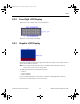
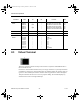
LCDS component Family contains a number of LCDs similar to the following:
The number of characters available for display changes depending on the LCD selected (e.g.,
16x1 in the LCD shown above). The controller for these devices is based on the Hitachi 44780
LCD controller.
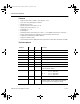
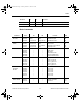
Pins on the LCDs are:
•
VCC — Supply Voltage
•
CV — Contrast Voltage
•
GND — Ground
•
RS — Instruction/Register Select
•
RW — Read/Write LCD Registers
•
E — Clock. Initiates data transfer within the LCD
•
D0 to D7 — Data I/O pins.
To set the LCD’s character set and trigger type:
1. Double-click on the placed LCD and click the Value tab.
2. Adjust the following as desired:
•
Base Character Set — choose one of: 0 for Hitachi; 1 for Intel/Motorola
•
Character Subset — if you chose 1 for the Base Character Set, choose one of: 28 for
European; 29 for Katakana; 30 for Cyrillic; 31 for Hebrew
•
Trig ge r Type — choose 0 for High Level; 1 for Falling Edge.
3. Click OK to close the dialog box and save the changes to the device.
ComponentRef.book Page 3 Thursday, December 7, 2006 10:12 AM